Electronic sound control circuit (applause)
This electronic sound control circuit works like a sound activated relay and can activate or deactivate a device connected to it, by two consecutive claps.
Applications for this circuit can be: activation / deactivation of lamps (light bulb operated by applause), water heaters, etc.
Electronic Sound Control Circuit Operation
When a clap is detected by the microphone (MIC), the signal is transmitted to the inverting input of the operational amplifier. The op amp compares its two inputs and outputs a signal that triggers the 555 timer IC which is configured as a monostable multivibrator.
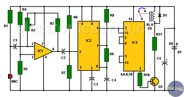
The 555’s output pulse activates the two clock inputs of the 4013 (2 D-flip-flops) integrated circuit.
The 4013 is configured as a 3-state counter, so it will take two claps before the flip-flop’s Q1 output goes high and turns on transistor Q1. Transistor Q1 in turn will activate the RLA relay. The relay works with 5v, and it is necessary to include the 220 ohm resistor in series to be able to use it with 9 volts. Diode D1 is used to protect transistor Q1.
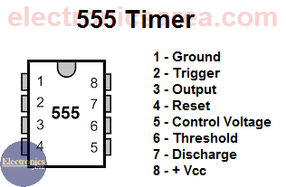
555 Timer PinOut
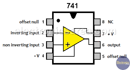
741 op amp Pinout
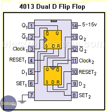
4013 – Dual D Flip Flop Pinout
List of circuit components
- 1 741 op amp (IC1)
- 1 555 timer (IC2)
- 1 4013 (Flip-Flop type D, Dual) integrated circuit (IC3)
- 1 2N2222 NPN transistor (NTE123) (Q1)
- 1 1N4001 diode or similar (D1)
- 4 0.1uF capacitors (C1, C2, C3, C4)
- 1 47uF electrolytic capacitor (C5)
- 5 10K resistors (R1, R2, R4, R5, R10)
- 1 15M resistor (R6)
- 1 10M resistor (R7)
- 1 100M resistor (R9)
- 1 1M resistor (R8)
- 1 220 ohm resistor (R11)
- 1 100K potentiometer (R3)
- 1 microphone (can be one of those used in recorders)
- 1 5V relay (RLA)
- 1 9 volt battery (B1)
Note: The circuit is connected to a 9 volt battery, but can be easily connected to a 12VDC source. In this case, the 5v relay is replaced by a 12v one and the 220 ohm resistor must be removed.
More Detector Circuits
- Light detector circuit using LDR (automatic night light)
- How to make a Light Sensitive Sound Generator Circuit?
- Light activated switch circuit with LDR and Op Amp
- Light Operated Relay Circuit using LDR / Photoresistor
- Twilight Switch Circuit
- Dark detector circuit using LDR and relay
- Darkness detector circuit with audio output using 555
- Temperature Gauge Circuit Using LM324 (PCB)
- Temperature to Voltage Converter using Thermistor (PCB)
- Rain Detector using two Transistors
- 2 LED Temperature Change Indicator with LM35 & 741
- Lie Detector Circuit Using Two Transistors
- Humidity sensor circuit using the 555 timer
- Blown Fuse Indicator Circuit using one transistor
- Electronic sound control Circuit (applause)
- Photodiode Amplifier Circuit – Current-to-Voltage Converter


