Rain detector using two transistors
This rain detector using two transistors, is a simple circuit that aims to alert the beginning of the rainfall.
The applications for this circuit can be many, but the most obvious is to alert people who have their clothes drying under the sun or the wind, to put them under the roof before they get wet again.
Its operation is easy to understand, and its few components make this circuit a very interesting project. The current consumption of the circuit is very low, being able to use 2 batteries of 1.5 V in series and thus obtain 3 volts.
How the rain detector works?
The two transistors (Q1, Q2), the two resistors (R1, R2) and the capacitor (C1) form an oscillator, which only works when current reaches the base of transistor Q1. When this oscillator is active, it reproduces a sound in the speaker.
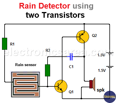
While the sensor terminals are not short-circuited (there is no current conduction due to a drop of water), transistor Q1 is in the cutoff region, consequently the transistor Q2 also enters the cutoff region and the oscillator does not work.
When the rainwater shortens the terminals of the sensor, a base current will enable the transistor Q1 which in turn will enable the transistor Q2. Transistor Q2 conducts and a current flows through the speaker, generating a sound. This process is repeated continuously while the sensor terminals are shorted.
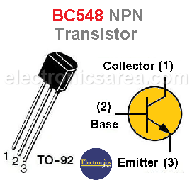
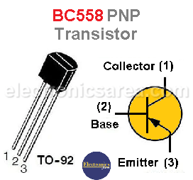
BC548 NPN transistor pinout & BC558 PNP transistor pinout
This circuit, due to its simplicity and few components, can be implemented to be portable on a small-sized printed circuit, powered by 2 1.5-volt batteries.
List of components for the rain detector circuit
- 1 BC548 NPN transistor or similar (Q1)
- 1 BC558 PNP transistor or similar (Q2)
- 1 330K resistor, 1/4 watt (R1)
- 1 10K resistor, 1/4 watt (R2)
- 1 0.01 uF (microfarads) capacitor (C1)
- 1 8 or 16 ohms small size speaker (spk).
More Detector Circuits
- Light detector circuit using LDR (automatic night light)
- How to make a Light Sensitive Sound Generator Circuit?
- Light activated switch circuit with LDR and Op Amp
- Light Operated Relay Circuit using LDR / Photoresistor
- Twilight Switch Circuit
- Dark detector circuit using LDR and relay
- Darkness detector circuit with audio output using 555
- Temperature Gauge Circuit Using LM324 (PCB)
- Temperature to Voltage Converter using Thermistor (PCB)
- Rain Detector using two Transistors
- 2 LED Temperature Change Indicator with LM35 & 741
- Lie Detector Circuit Using Two Transistors
- Humidity sensor circuit using the 555 timer
- Blown Fuse Indicator Circuit using one transistor
- Electronic sound control Circuit (applause)
- Photodiode Amplifier Circuit – Current-to-Voltage Converter


