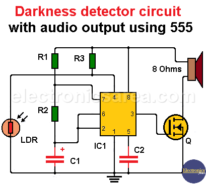
Darkness detector circuit with audio output using 555
This darkness detector circuit beeps when the light drops below a certain level. The main elements of this darkness detector circuit are the 555 integrated circuit, that is configured to operate as a stable multivibrator and an LDR (light dependent resistor) which is used as darkness sensor.
Darkness detector circuit operation
Pin 4 of the 555 timer is the enabling pin of the integrated circuit. The 555 IC will begin to work only when the voltage level on this pin is on high level.
Darkness detector circuit with audio output using 555
The LDR and resistor R3 form a voltage divider. When the LDR does not get enough light, its resistance increases and the voltage across its terminals rises to almost the voltage level of the power source. When this happens, the 555 is enabled and starts to work.
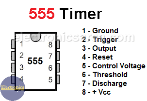
555 Timer Pin Out
When the 555 is active, it delivers on its output (pin 3) a square wave. This square wave causes the MOSFET transistor passes continuously from the cutting region to the saturation region, sounding the speaker.
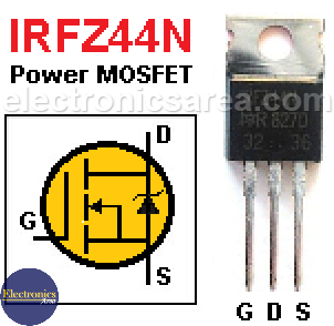
IRFZ44N Power MOSFET
If the light level increases, the voltage level on pin 4 decreases, the 555 timer is disabled and the audio signal is interrupted.
To better control the level of light or darkness, which causes the circuit starts its operation, the resistor R3 is replaced by a 1K resistor in series with a 100K potentiometer. By varying the potentiometer, you can make the adjustments.
Darkness detector circuit components
- 1 555 timer (IC1)
- 1 LDR (photo resistor)
- 1 47K resistor (R1)
- 1 1K resistor (R2)
- 1 10K resistor (R3)
- 1 0.047uF electrolytic capacitor (C1)
- 1 0.1uF capacitor (C2)
- 1 IRFZ44 MOSFET Transistor (Q)
- 1 8 or 4 ohms speaker
More Detector Circuits
- Light detector circuit using LDR (automatic night light)
- How to make a Light Sensitive Sound Generator Circuit?
- Light activated switch circuit with LDR and Op Amp
- Light Operated Relay Circuit using LDR / Photoresistor
- Twilight Switch Circuit
- Dark detector circuit using LDR and relay
- Darkness detector circuit with audio output using 555
- Temperature Gauge Circuit Using LM324 (PCB)
- Temperature to Voltage Converter using Thermistor (PCB)
- Rain Detector using two Transistors
- 2 LED Temperature Change Indicator with LM35 & 741
- Lie Detector Circuit Using Two Transistors
- Humidity sensor circuit using the 555 timer
- Blown Fuse Indicator Circuit using one transistor
- Electronic sound control Circuit (applause)
- Photodiode Amplifier Circuit – Current-to-Voltage Converter


