Dark detector circuit using LDR and relay
This dark detector circuit uses as a main component an LDR. An LDR changes its resistance value depending on the amount of light it receives. The more light means less resistance, the less light means more resistance. To activate the output (for example a lamp), a relay is used
How the Dark detector circuit works?
Note: LDR = Light Dependent Resistor = Photoresistor.
The set R2, VR1 (potentiometer) and R4 (LDR), form a voltage divider. The output voltage of this voltage divider is taken at the junction of the LDR and the potentiometer.
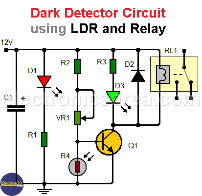
- When the photoresistor receives light, there is a low voltage at the base pin of the transistor. The transistor is in the cut-off region, there is no collector-emitter current and the relay will not activate.
- When the LDR receives no light, the voltage at the base pin of the transistor rises high enough to put the transistor into the saturation region, there is collector-emitter current and the relay is activated.
-

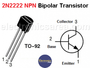
- 2n2222 BJT Pinout
As the level of illumination on the LDR gradually changes, a potentiometer is used to set the appropriate voltage level for activation of the relay.
LED D1 indicates that the circuit is in operation, and LED D3 lights when the light level decreases. The semiconductor diode D2 is used to protect the transistor when the relay is switched off.
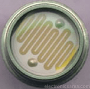
LDR – Light Dependent Resistor
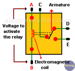
Maybe you want to know why is there a diode connected in parallel to a relay coil?
Dark detector circuit list of components
- 1 2N2222A NPN transistor (Q1)
- 2 green and red LEDs, (D1, D3)
- 1 1N4001 semiconductor diode (D2)
- 2 1K, 1/4W resistors (R1, R3)
- 1 10K, 1/4W resistor (R2)
- 1 LDR / photoresistor (R4)
- 1 47K potentiometer / variable resistor (VR1)
- 1 10uF / 25 volts or more electrolytic Capacitor (C1)
- 1 12 volts relay (RL1)
More Detector Circuits
- Light detector circuit using LDR (automatic night light)
- How to make a Light Sensitive Sound Generator Circuit?
- Light activated switch circuit with LDR and Op Amp
- Light Operated Relay Circuit using LDR / Photoresistor
- Twilight Switch Circuit
- Dark detector circuit using LDR and relay
- Darkness detector circuit with audio output using 555
- Temperature Gauge Circuit Using LM324 (PCB)
- Temperature to Voltage Converter using Thermistor (PCB)
- Rain Detector using two Transistors
- 2 LED Temperature Change Indicator with LM35 & 741
- Lie Detector Circuit Using Two Transistors
- Humidity sensor circuit using the 555 timer
- Blown Fuse Indicator Circuit using one transistor
- Electronic sound control Circuit (applause)
- Photodiode Amplifier Circuit – Current-to-Voltage Converter


")
