Light Operated Relay Circuit using LDR
This Light Operated Relay Circuit using LDR is very interesting. The LDR varies its value (ohms) depending on the amount of light that illuminates it. The more light less resistance and less light more resistance.
A potentiometer is used to control the light level that activate the relay.
How the Light Operated Relay Circuit works?
Note: LDR = Light Dependent Resistor = Photoresistor
– When the LDR is illuminated, its resistance is low and causes the voltage at the base of transistor Q1 goes up. The transistor Q1 enters its saturation region, and causes the transistor Q2 to enter the cut-off region. There is no current flow between the collector and the emitter of the transistor Q2, so the relay is not activated.
– When the LDR is not illuminated, its resistance is high and causes the voltage at the base of the transistor Q1 goes down. The transistor Q1 enters its cut-off region and causes the transistor Q2 to enter its saturation region. There is current flow between the collector and the emitter of the transistor Q2, so the relay is activated.
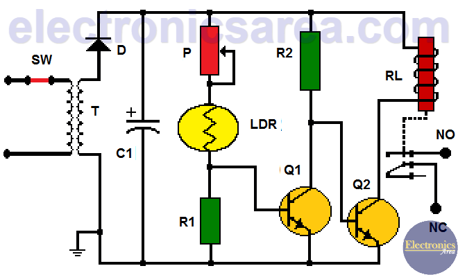
Light Operated Relay Circuit using LDR
The LDR resistance value is not critical and almost any can be used, since a potentiometer is placed in series to control the sensitivity of the circuit.
Powering the circuit
A very simple circuit is used to obtain the DC voltage required for the Light Operated Relay Circuit to work.
A half-wave rectifier with only one diode is used. The rectified signal is flattened with the C1 electrolytic capacitor. The resulting voltage is far from flat, but the circuit does not need more.
It is always possible to replace the rectifier diode with a diode bridge to obtain a full wave rectifier.
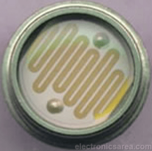
LDR = Light Dependent Resistor = Photoresistor
Another light activated circuit you can see is the Light activated switch with LDR and an Op. Amp.
Circuit component list
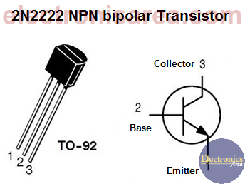
- 2 NPN 2N2222 transistors (NTE 123) or equivalent (Q1, Q2)
- 1 47 KΩ potentiometer (P)
- 1 1 MΩ resistor (R1)
- 1 4.7 KΩ resistor (R2)
- 1 1000 uF (microfarads), 16 volts electrolytic capacitor (C1)
- 1 1N4002 or equivalent rectifier diode (D1)
- 1 LDR (Light Dependent Resistor)
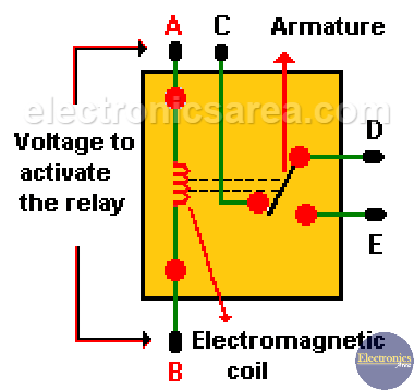
- 1 12V relay, with the highest possible winding resistance, (500 ohms or more) (RL)
- 1 110/220 to 9 volts transformer, of 500 milliamperes. (T)
- 1 switch (SW)
Notes:
- N.O. = Normally Open contact
- N.C. = Normally Closed contact
More Detector Circuits
- Light detector circuit using LDR (automatic night light)
- How to make a Light Sensitive Sound Generator Circuit?
- Light activated switch circuit with LDR and Op Amp
- Light Operated Relay Circuit using LDR / Photoresistor
- Twilight Switch Circuit
- Dark detector circuit using LDR and relay
- Darkness detector circuit with audio output using 555
- Temperature Gauge Circuit Using LM324 (PCB)
- Temperature to Voltage Converter using Thermistor (PCB)
- Rain Detector using two Transistors
- 2 LED Temperature Change Indicator with LM35 & 741
- Lie Detector Circuit Using Two Transistors
- Humidity sensor circuit using the 555 timer
- Blown Fuse Indicator Circuit using one transistor
- Electronic sound control Circuit (applause)
- Photodiode Amplifier Circuit – Current-to-Voltage Converter

")

