Electronics Area – Electrical and Electronics Tutorials and Circuits
Welcome to Electronics Area
Electrical and Electronics Tutorials and Circuits
Recent posts
Differential Temperature Controller (PCB)
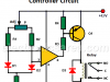
This circuit measures the temperature difference between 2 sensors and activates a relay when they are different. It is also possible to detect a temperature change, even when the two measured temperatures are normally different.
Iron Core Inductor
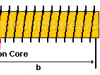
The iron core inductor has very special magnetic characteristics. What they do is to reinforce the magnetic field. The magnetism of the core material depends on the bias of “the molecular magnetic domains”
Benjamin Franklin’s Fluid Theory

Benjamin Franklin imagined the electricity as a invisible fluid. Franklin assured that if any body had more fluid than usual, it could have a positive charge, but if it had less fluid than normal it had negative charge.
Digital Logic Levels (hight, low, 1, 0)
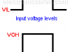
In digital circuits, it is common to say that we have a “high or a “low” logic level at the input or output of a circuit. If we have a “high” level we say it is a “1” and if we have a “low” level we say that it is a “0”.
LDR – Photoresistor
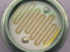
What is an LDR – Photoresistor? LDR (Light Dependent Resistor) is light sensitive resistor whose resistance changes with the light intensity that falls upon it.
Resonance in an RLC Circuit
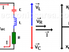
Resonance in RLC Circuits is a special condition for parallel and series RLC circuits, when capacitive reactance and inductive reactance have the same magnitude and cancel each other. This only happens at frequency fo.
Ebers Moll Model of a Bipolar Transistor
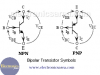
Ebers Moll Model of a Bipolar Transistor
The bipolar transistor is an electronic device that originates a big evolution in the electronics field. The basic features of the bipolar transistor are introduced on this topic. We’ll study the basic model (Ebers Moll Model) of these devices and their use in the analysis of circuits biasing.
Impedance of Inductor
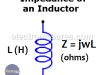
The impedance of an inductor (also called inductance) is the measure of the opposition to a change of electrical current in this component.
Power in AC Circuit
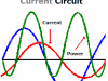
Electric power. Electrical power on a circuit with reactive load (reactance). How to obtain the current in a circuit having resistance and reactance.
Aiken code – Excess 3 code
Aiken BCD code is similar to the natural BCD code, but with “weights” or “values” distributed differently. The Excess 3 Code is obtained by adding “3” to each combination of the natural BCD code.
JK Flip-Flop
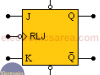
The JK Flip-Flop is a sequential device with 3 inputs (J, K, CLK (clock signal)) and 2 outputs (Q and Q’). J and K are control inputs.
FET – Field Effect Transistor (JFET)
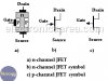
FET (JFET)
Field effect transistor or FET is a particularly interesting transistor and it can be of two types: the Junction Field Effect Transistor or JFET and the Metal-Oxide Semiconductor Field Effect Transistor (MOSFET).