Electronics Area – Electrical and Electronics Tutorials and Circuits
Welcome to Electronics Area
Electrical and Electronics Tutorials and Circuits
Recent posts
Combinational Circuit
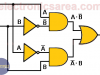
A combinational circuit is a circuit where the output depends only on the combination of the inputs at the time we are testing the output
Sequential Circuit – Digital Logic
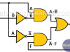
A sequential circuit is a circuit where there are one or more feed backs from one or more outputs. The new output depend on the inputs and the last output
Logic AND Gate – AND Truth Table
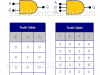
The logic AND gate is one of the simplest gates in Digital Electronics. The output of an AND gate is true (“1”) only when all inputs are true (“1”). If one or more inputs are false (“0”), then the output is false (“0”).
OR and AND logic gates made with diodes
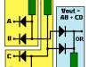
Diode Logic OR gate (wired OR connection) and Diode Logic AND gate (wired AND connection). Diode Logic uses the fact that diodes conduct only in one direction. (they behave like switches)
XOR Logic Gate
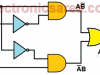
In digital electronics there are special gates. One of them is the XOR logic gate or exclusive OR gate. Equivalent XOR Logic Gate using common logic gates
Op Amp Voltage follower / Voltage Buffer
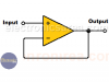
A buffer has an output that is exactly like the input. This feature is very useful for solving impedance matching problems.
Op Amp Open Loop Gain – Op Amp Open Loop Configuration
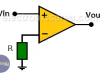
Op Amp Open Loop Gain – The open loop gain of the operational amplifier is given when there is no feedback path between the output and either input
Transformer Structure
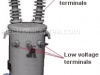
Electric Power Transformer Structure. All electric transformers, have three fundamentals parts: high voltage winding, low voltage winding and Core.
Impedance matching Transformer
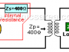
An impedance matching transformer is used to couple an antenna to a transmission and / or reception equipment. It was widely used in the coupling of the antenna to the analog television, by radio amateurs
Impedance (Z) = (Resistance + Reactance)
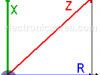
Impedance (Z) shows the opposition to the flow of direct or alternating current. Impedance is the vector addition of resistance (R) and reactance (X).
Clock signal generator using 7400 IC (PCB)
Clock signal generator using 7400 IC. This clock generator is an astable circuit which uses the TTL 7400 (four 2 inputs NAND gates) integrated circuit. Suggested Printed Circuit Board (PCB)
UJT Relaxation oscillator circuit
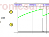
The UJT relaxation oscillator circuit is a non-linear oscillator used to generate a non-sinusoidal repetitive output signals that can trigger power control devices such as SCRs and TRIACs.