What is Resonance in an RLC Circuit?
Resonance in an RLC Circuit is a special condition for parallel and series RLC circuits, when capacitive reactance and inductive reactance have the same magnitude and cancel each other. This only happens at some frequency named resonance frequency (fo).
Resonance in a series RLC circuit
When an alternating current (I) flows through an inductor and a capacitor connected in series, voltage at the terminals of this LC circuit is zero (0) or almost zero volts, for some frequency “fo” of the applied signal. This only happens when the voltage at the terminals of the inductor L and the voltage at the terminals of the capacitor C are equal in magnitude but opposite in phase.
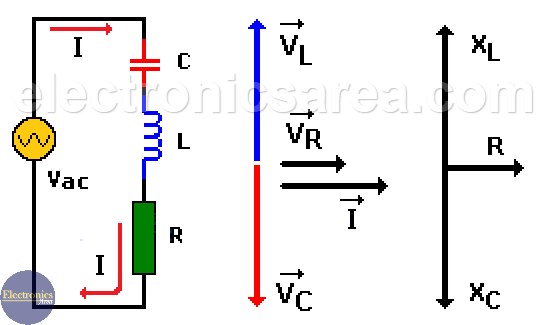
In other words: VL=VC, where: VL = (I)(XL), VC = (I) (XC). Since these two components are in series, the electric current (I) flowing through them is the same, then XL = XC. We know that:
- XL = 2πfoL = woL
- XC = 1/(2πfoC) = 1/(woC)
where: wo = 2πfo.
Equating the absolute values of XL and XC;
where “fo” is the resonant frequency.
The resistor in the image can be the resistive value of the inductor coil or a resistor element needed to set the quality factor “Q” of the circuit. A quality factor “Q” is a measure of the selectivity. In a series RLC circuit, the smaller the value of the resistor, the higher the quality factor Q for given values of L and C.
For a Series RLC circuit in resonance, the impedance is minimum. As you can see from the image above, if VC = VL, there is only VR and VR depends only on R.
Resonance in a Parallel RLC circuit
A similar condition exists when an inductor and a capacitor are connected in parallel. In this case, for a Parallel RLC circuit in resonance, the impedance is maximum.
When an inductor and a capacitor are connected in parallel, the current given by the source is zero (0) or almost zero amps, for some frequency “fo” of the applied signal. This only happens when the current in the inductor L and the current in the capacitor C are equal in magnitude but opposite in phase.
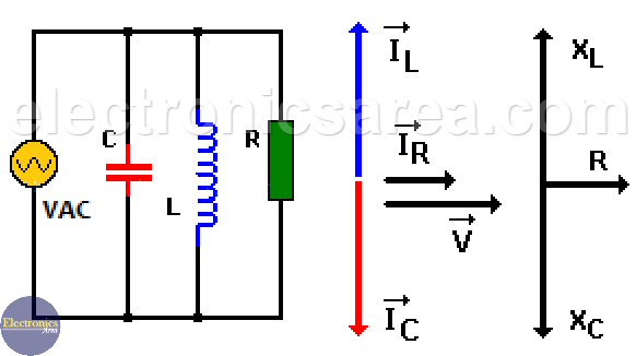
In other words: IL = IC, where IL = VL/XL, IC = VC/XC.
In this circuit IL=IC, where: VL = (IL)(XL), VC=(IC)(XC). Since these two components are in parallel, the voltage is the same, then XL = XC. We know that:
- XL = 2πfoL = woL
- XC = 1/(2πfoC) = 1/(woC)
where: wo = 2πfo.
Equating the absolute values of XL and XC;
where “fo” is the resonant frequency.
")


")