Home / Circuits / Controllers /
Differential Temperature Controller circuit
The Temperature Difference Controller circuit measures the temperature difference between two sensors and activates a relay if the temperature is not the same. It is also possible to detect a temperature change even when the two measured temperatures are normally different.
How does the differential temperature controller work?
To implement this circuit, we use two common semiconductor diodes (D1 and D2) as temperature sensors. The anodes of the diodes are connected to the inputs of the operational amplifier. The op-amp works as a comparator, and any temperature difference will cause a low voltage level at the output of the comparator.
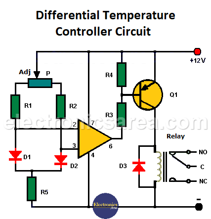
Diodes are placed in two different locations to measure the two temperatures we want to compare. If there is a small change in the temperature of either diode, the voltage at its terminals will decrease.
- If the D1 diode is placed in a location susceptible to temperature drop, the op-amp will have a low voltage level at its output and will activate the relay through transistor Q1. The transistor can activate a heater or similar device.
- If the D2 diode is placed in a location susceptible to temperature rise, the operational amplifier will have a low voltage level at its output and will activate the relay through transistor Q1. The transistor can activate a cooling system or fan.
An approximate result view of the final circuit
When the temperature on the two diodes is equalized, the relay will de-energize. Note that the inclusion of the potentiometer may alter the operation of the circuit.
Note: The circuit can be powered by a 9V battery. You will need to switch the relay with one of the same voltage.
List of circuit components
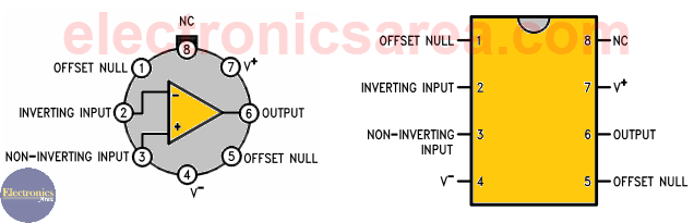
- 1 741 Operational Amplifier (IC1)
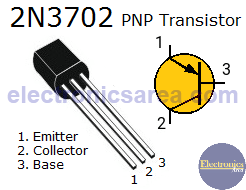
- 1 2N3702 PNP bipolar transistor or equivalent (Q1)
- 2 4.7K resistors (R1, R2)
- 2 1.2K resistors (R3, R4)
- 1 2.7K resistor (R5)
- 1 100K potentiometer (P)
- 3 1N4001 diodes (D1, D2, D3)
- 1 12V relay (RL1)
Differential Temperature Controller Suggested PCB
More Controller circuits
- Water Level Controller using Transistor and Relay
- Automatic Water Level Controler
- Water level controller using NOR gates
- Differential Temperature Controller (PCB)
- Soldering Iron Temperature Controller
- Heat control using thermistor and TRIAC
- Thermistor Controlled AC Fan
- Electronic Thermostat using transistors
- H-Bridge DC Motor Control
- DC motor speed controller using 555
- DC Motor Speed Control with 4049
- Dimmer / AC Motor Speed Controller using TRIAC


")