What is a JK Flip-Flop?
The JK Flip-Flop is a sequential device with 3 inputs (J, K, CLK (clock signal)) and 2 outputs (Q and Q’). J and K are control inputs. These control inputs are named “J” and “K” in honor of their inventor, Jack Kilby.
JK Flip-Flop is called as a universal Flip-Flop or a programmable flip-flop because using its J and K inputs, the other Flip-Flops can be implemented.
The PRESET and CLEAR inputs of a JK Flip-Flop
There are two very important additional inputs in the JK Flip-Flop.
- The PRESET input is used to directly put a “1” in the Q output of the JK Flip-Flop.
- The CLEAR input is used to directly put a “0” in the Q output of the JK Flip-Flop.
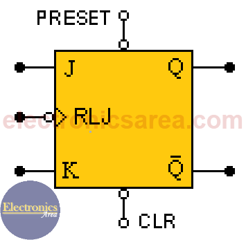
The PRESET and CLEAR inputs of the JK Flip-Flop are asynchronous, which means that they will have an immediate effect on the Q and Q’ outputs regardless of the state of the clock and / or the J and K inputs.
It is important NOT to simultaneously activate the CLEAR and PRESET inputs.
The Flip-Flop may or may not have a small bubble in the PRESET or CLEAR inputs which indicate that they are active low. The complete diagram of the JK flip-flop is as shown in the diagram above.
JK Flip-Flop Truth Table
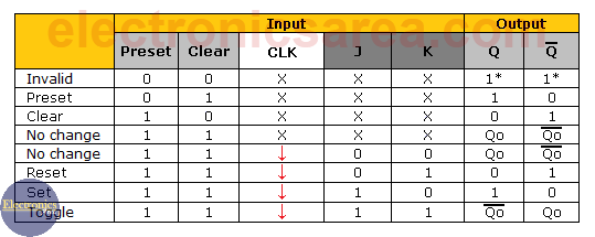
From the previous truth table it can be seen that the CLEAR (CLR) and PRESET inputs are active at a low logic level and put on the Q output of the Flip-Flop, a high logic level regardless of the state of the clock and / or the state of the J and K inputs. (see the J, K and clock inputs with an “X”).
In order for the J and K inputs and the clock to be functional, the CLEAR and PRESET inputs must be at a “High” logic level (not active), then:
- If inputs are: J = 0 and K = 0, there is a memory or retention state (it keeps the output it had before the entries had changed). (Memory no change)
- If inputs are: J = 0 and K = 1, Q is set to “0” and Q’ to a “1” (Reset)
- If inputs are: J = 1 and K = 0, Q is set to “1” and Q’ to “0”. (Set)
- If inputs are: J = 1 and K = 1, the outputs Q and Q’ of the flip-flop change from a logical level to the opposite (“0” to “1” or “1” to “0”). (Toggle)
The above has effect only when the clock pulse is on the falling or trailing edge (see the arrow in the “Clock” column)
Notes:
- Toggle = change of state. If it was at “1” it goes to “0” and vice versa
- FF = Flip-Flop = Flip Flop
More Digital Tutorials
- What is the difference between Analog & Digital?
- What is a logic circuit?
- Digital logic levels (high, low, 1, 0)
- The truth table
- Boolean algebra
- Karnaugh Map (K-map)
- Binary number system
- Hexadecimal numbering system
- BCD code – binary coded decimal
- Gray code – Gray code table
- Aiken code – Excess 3 code
- AND gate
- NAND gate
- OR gate
- NOR gate
- NOT gate
- XOR gate
- How to build a NAND gate with transistors & diodes?
- OR & AND logic gates made with diodes
- The combinational circuit
- The sequential circuit
- JK Flip-Flop
- What is a binary decoder?


