What are Logic Levels?
In digital circuits and components like the NOR gate, it is common to say that we have a “high or a “low” logic level at the input or output of a circuit. If we have a “high” level we say it is a “1” and if we have a “low” level we say that it is a “0”.
If we were using a TTL IC which works with +5 volts, the “1” would be a +5 volts voltage level and the “0” would be a 0 volts voltage level. This is the ideal case in digital circuits.
TTL, CMOS and HC logic levels (voltage levels)
In the real world, these values are different. Digital integrated circuits work with input and output values that vary according to the integrated circuit technology.
The table above gives us a range of values for the “high” and “low” logic levels for different logic families.
In the TTL family, a logical “0” means that the voltage level is between 0 and 0.8 volts and a logical “1” means that the voltage level is between 2 and 5 volts.
In the CMOS technology, a logic “0” means that the voltage level is between 0 and 1.5 Volts and a logic “1” means that the voltage level is between 3.5 and 5 Volts.
Logic Levels Characteristics
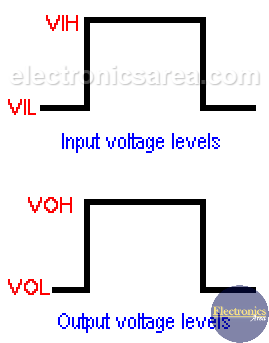
- A high level input voltage is called VIH
- A low voltage input is called VIL
- A high level output voltage is called VOH
- A low output voltage is called VOL
In addition to the voltage levels, we must also take into account the currents at the inputs and outputs of these circuits.
- The high level current input is: IIH
- The low level current input is: IIL
- The high level current output is: IOH
- The low level current output is: IOL
These output currents values can be obtained with the Ohm’s law: Io = Vo / RL. Where:
- Io: is the output current
- Vo: is the output voltage
- RL: is the load or its equivalent circuit connected to the output.


