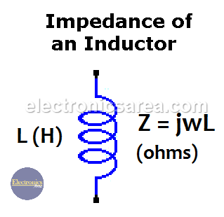
What is the Impedance of an Inductor?
Impedance of inductor and impedance of capacitor are special cases of the general representation of impedance. Impedance of an inductor (also called inductance or inductive reactance) is the measure of the opposition to a change of the electrical current in this component.
It can be summarized, in a very general way, that an inductor lets the low frequencies signals pass (including the 0 Hz signals) and blocks the high frequencies signals.
The formula of the impedance of inductor is: Z = jLw, where:
- Z: is the impedance in ohms
- j: is the operator for imaginary numbers. (imaginary unit)
- L: is the value of the inductor in Henries (H)
- w: is equal to 2.π.f, where the letter f represents the frequency of the signal applied to the inductor. (frequency unit is Hertz).
Inductor impedance (inductive reactance).
Usually, inductors are used in circuits with a frequency of signals different from zero (0Hz).
We can see, from the impedance formula in an inductor, that the impedance is proportional to the frequency. This means that if the frequency is zero (0 Hz) the impedance is zero.
Now if the impedance is zero, the voltage at the inductor terminals is also zero. (V = 0 volts) and there is a short circuit in the inductor. In this case, the current flows freely to its maximum possible value.
The impedance has a general formula: Z = V / I (RMS voltage / RMS current). This formula is similar to the ohm law, which is applied to resistors, but in this case it is used for AC signals.
The “j” operator.
The reason why this operator is used in electronics is that there is a phase difference between the voltage and the current in inductors. This phase difference is 90° or π/2 and the voltage is ahead of the current by 90°. (90 degrees). The frequency of alternating voltage and the alternating current in the inductor is the same.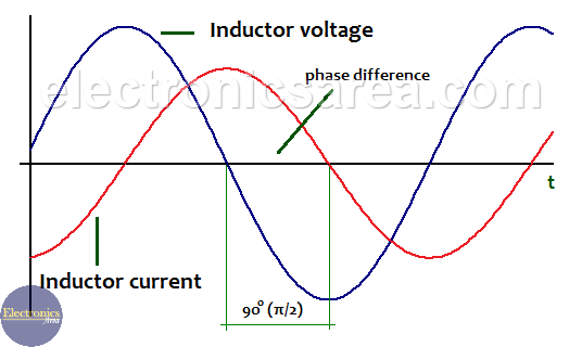
Phase difference between voltage and current in an inductor
The “j” operator is not used with resistors because there is no phase difference between voltage and current. In other words, the voltage and current in a resistor are in phase.
w (angular frequency).
The value w depends directly on f (the frequency) and is measured in radians/sec. (w = 2.π.f)
For example, for a frequency of 300 Hz, w = 2.π.f = 2 x (3.1416) x 300 = 1884.96 rad / sec.
How to calculate the Impedance of inductor?
To calculate the inductance of an inductor, we use the formula Z = wL.
Example 1:
How to obtain the impedance of a 25 mH inductor at 300 Hz.
Z = 2 x π x 300hz x 25mH = 2 x (3.1416) x 300 x 0.025 = 47.124 ohms
Example 2:
How to obtain the impedance of a 25 mH inductor at 50 Hz?
Z = 2 x π x 300hz x 25mH = 2 x (3.1416) x 50 x 0.025 = 7.854 ohms.
It can be seen from the two previous examples, where the value of the inductor is the same (25 mA), that the impedance is higher for higher frequencies. It can be summarized that the inductor let pass low frequencies signals (there is low impedance) and blocks the high frequencies signals (there is high impedance).
Example 3:
How to obtain the impedance of a 12 mH inductor at 60 Hz?
Z = 2 x π x 60hz x 12mH = 2 x 3.1416 x 60 x 0.012 = 4.524 ohms.
More Inductor tutorials
- Inductor – Inductance
- Series inductors and parallel inductors
- Inductor in DC and AC. Quality factor
- Impedance of Inductor
- Air core inductor inductance calculation
- Iron Core Inductor


