Electronics Area – Electrical and Electronics Tutorials and Circuits
Welcome to Electronics Area
Electrical and Electronics Tutorials and Circuits
Recent posts
Current Divider Rule in parallel resistors
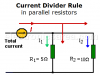
By using the current divider rule, we can find the current in each resistor connected in parallel. The electric current passing through a circuit of two resistors in parallel is divided in two.
12 to 5 volt Converter Circuit (for cars)
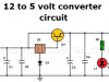
This 12 to 5 volt converter circuit is very useful. It can be used to connect 5 volt electronic devices in a car with a 12 volt battery. (Automotive lead-acid batteries can be up to 13.7 volts).
Logic OR gate – Symbol & Truth Table
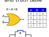
The logic Or gate is one of the simplest digital logic gates. The output of this gate is “High”, when one or all of its inputs are “High”. We can also say that, the output of an OR gate is “Low” only when all gate inputs are “Low”.
12 volt Power Supply using the 7805 regulator
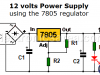
This 12 volt power supply circuit is simple and very useful. Sometimes a 12 Volt power source is needed, and we only have 5 or 9 volt regulators (7805, 7809)
Flashing LEDs Circuit for Pedestrians using NAND gates
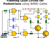
This is a simple flashing lights circuit uses high-intensity white LEDs that turn on and off continuously. It may be placed in any part of the body, such as an arm.
Continuity tester using 741 IC
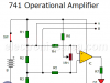
A good application for this circuit would be to test welds made on a printed circuit board. It could also be used to test continuity of wires, connections, etc.
Thermistor Controlled Fan Circuit – AC Fan
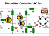
This circuit varies the speed of a fan plugged into a 110- or 220-volt outlet using only three transistors and a few additional components
Measuring Low Resistances
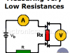
There are cases where the resistance is too low and a direct use of the ohmmeter is not practical. So a special method is needed
NAND Gate – The Universal Gate
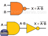
The NAND gate, also called a universal gate, is a gate that produces a logic “0” output only when all logic inputs are “1”. The NAND gate truth table
The logic NOT Gate – Symbol, Truth Table
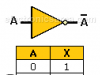
The NOT gate is a logic gate that has only one input and one output. The output logic level is the opposite of the input logic level
Measure Resistance with an Analog Multimeter

How to use the analog multimeter / VOM to measure resistance (ohms). How to use the range selector and how to set the needle to zero ohms.
How to Make a Current Flow Indicator?
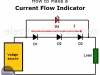
This Electric Current Flow Indicator gives a visual indication that there is a current flow. Possible applications for this small circuit may be: a battery charger, a voltage power source, etc.
In order to achieve our objective we place 3 rectifier diodes in series, which in turn are in series with the load / battery.