The NOT gate
In digital electronics, not much could be achieved without the NOT gate, also called the inverting gate. The symbol and truth table are shown below. The NOT gate, like the AND gate and the OR gate, is very important. This gate delivers at its output the inverse (opposite) of what is at the input.
The output of a NOT gate has the inverse value of its input. It is seen from the truth table below that the output X = A. This means that:
- If we have a logical “1” at the input, there will be a logical “0” at the output and…
- If we have a logical “0” at the input, there will be a logical “1” at the output.
NOT gate Truth table
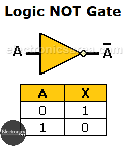
Note: The apostrophe in the following expression means inverted. So: X = A’ is the same as X = A
NOT gates in cascade
NOT gates can be cascaded. In this way, after two gates, an output equal to the original input is achieved. See the following image and the truth table
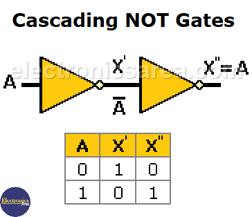
Cascading NOT gates
One reason to implement a circuit where you have the same thing at the output as you have at the input is the desire to achieve a delay of the original signal for a special purpose.
The NOT gate in different technologies
- 74LS04 – contains 6 NOT gates. (Low-power Schottky TTL Logic Gate Chip.)
- 74HC04 – high-speed CMOS option. (Low-power, high-speed CMOS Logic Gate Chip)
- CD4069 – widely used in electronic projects. (Low Power, High Speed standard CMOS)
- CD4049 – inverter buffer with superior current handling capacity.
Example of NOT gates in TTL technology: the SN7404 integrated circuit. (6 NOT gates in a single chip)
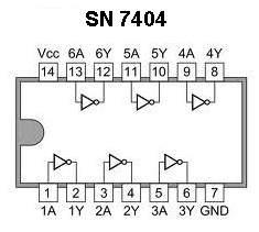 Six Independent Hex Inverters
Example of NOT gates in CMOS technology: the 4049 integrated circuit. (6 NOT gates in a single chip)
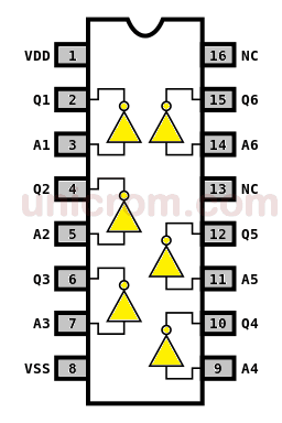
Standard CMOS CD4049 – 6 Independent Inverting Buffers
You may also like: Logic probe using NOT gates
More Digital Tutorials
- What is the difference between Analog & Digital?
- What is a logic circuit?
- Digital logic levels (high, low, 1, 0)
- The truth table
- Boolean algebra
- Karnaugh Map (K-map)
- Binary number system
- Hexadecimal numbering system
- BCD code – binary coded decimal
- Gray code – Gray code table
- Aiken code – Excess 3 code
- AND gate
- NAND gate
- OR gate
- NOR gate
- NOT gate
- XOR gate
- How to build a NAND gate with transistors & diodes?
- OR & AND logic gates made with diodes
- The combinational circuit
- The sequential circuit
- JK Flip-Flop
- What is a binary decoder?


