1 AND Gate – 2 OR Gate – 3 NAND Gate – 4 NOR Gate – 5 XOR Gate – 6 NOT Gate
What is an OR gate?
The OR gate, like the AND gate, is one of the simplest digital logic gates. The output of this gate is high if one or all of its inputs are high. We can also say that the output of an OR gate is low only when all of its inputs are low.
This gate is represented by the Boolean function: X =A+B for a 2 input OR gate, X = A+B+C for a 3 input gate, X = A+B+C+D for a 4 input gate and so on.
Two-input OR gate and truth table
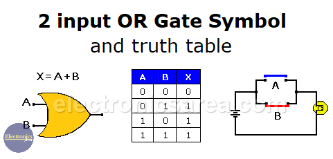
The following figure shows the symbol of a 2-input OR gate and its truth table.
It also shows how the 2-input OR logic function can be performed using switches. Closing the A switch “OR” the B switch turns on the light. “1”= closed, “0”= open, “0”= light off, “1”= light on.
The lamp will turn ON when one of the switches (A or B) is closed. This is because when one of the switches is closed, an electric current flows through the lamp. The Boolean function is: X = A+B.
You may also want to know how to make an OR gate with diodes
An interesting logic gate to look at is the XOR gate, which has a “0” output when A and B inputs are “1”. Look at the truth table of the 2-input OR gate.
Three-input OR gate and truth table
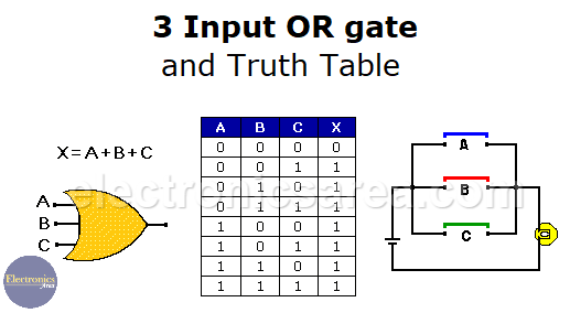
The following figure shows the symbol of a 3-input OR gate and its truth table.
It also shows how the 3-input OR logic function can be performed using switches. Closing switch A “OR” switch B “OR” switch C turns on the light. “1”= closed, “0”= open, “0”= light off, “1”= light on.
The lamp turns ON when one of the switches (A or B or C) is closed. This is because when one of the switches is closed, an electric current flows through the lamp. The Boolean function is: X = A+B+C.
If we want to have the opposite behavior, say the light bulb is turned on when all the switches are open, then the NOR gate must be used.
Notes:
- “0”, “Low” and “OFF” have the same meaning.
- “1”, “High” and “ON” have the same meaning.
1 AND Gate – 2 OR Gate – 3 NAND Gate – 4 NOR Gate – 5 XOR Gate – 6 NOT Gate


