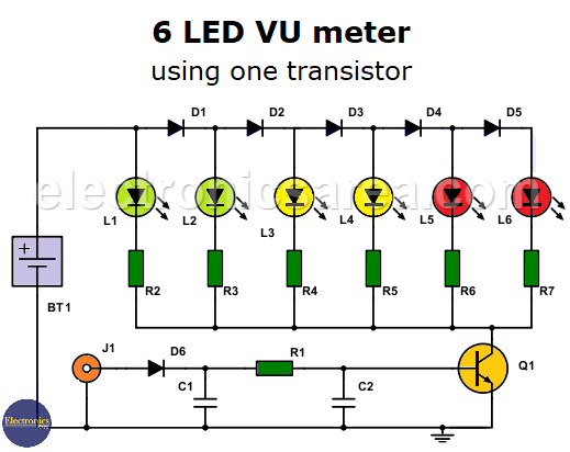
6 LED VU meter circuit with one transistor
This simple 6 LED VU meter using a single transistor allows us to visualize the level of an audio signal. Due to its few components, it is a cheap circuit and easy to build. The components are very common and easy to get.
The interesting thing about this circuit is that it uses a single transistor as an active component, and its operation affects the behavior of the entire circuit.
The progression of the illumination of the LEDs is linear, not logarithmic.
How does the transistorized 6 LED VU meter work?
The audio signal is applied directly to diode D6. Diode D6 rectifies the incoming audio signal, which is then passed to capacitor C1. C1 flattens the signal and produces a DC voltage at its terminals proportional to the audio signal.
The resistor R1 and capacitor C2 set helps to eliminate the small voltage variations that may exist before the signal is applied to the base of the bipolar transistor Q1.
Diodes D1 through D5 create a voltage difference of approximately 0.6 volts between each LED. Thus, an LED will light up after a 0.6 volt increase across the entire set of LEDs. Transistor Q1 works in its active region and …
- The closer the collector-emitter voltage (VCE) is to the saturation region, the more LEDs will light.
- The closer the collector-emitter voltage (VCE) is to the cutting region, the fewer LEDs will light.
6 LED VU meter using a single transistor
The collector-emitter voltage of the transistor, which controls how many LEDs light up, depends on the level of the audio signal applied to the base of the transistor.
You may be interested in the 8 LED VU meter circuit or an Audio level meter circuit.
List of 6 LED VU meter components
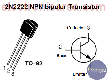
- 1 2N2222 NPN transistor or similar (Q1)
- 6 1N4148 diode or similar (D1, D2, D3, D4, D5, D6)
- 1 1N4148 silicon diode / 1N60 germanium diode or similar (D6) (see note below)
- 6 LEDs, 2 green, 2 yellow or amber, 2 red (L1, L2, L3, L4, L5, L6)
- 1 82K resistor (R1)
- 4 330 Ohm resistors (R2, R3, R4, R5)
- 2 390 Ohm resistors (R6, R7)
- 1 1 uF (microfarad) capacitor (C1)
- 1 10 uF capacitor (C2)
- 1 9-Volt Battery or 9-Volt Power Source (BT1)
1 Audio Input Connector (J1)
Note: To make this VU meter more sensitive and to activate with weaker audio signals, you can replace the 1N4148 silicon diode (D6) 1N4148 with the germanium diode 1N60.
If you make this change, you must change the value of the R1 resistor to 2.2K and eliminate the C1 capacitor.
More Audio Circuits
- 2 watt audio amplifier with the TDA2822M IC
- 6 watt audio amplifier with TDA2613 (Hi-Fi)
- 400 watt stereo amplifier with STK4050
- 4-channel audio mixer using LM3900 IC
- Microphone mixer using operational amplifiers
- 6 LED VU meter using a single transistor
- Audio splitter – 1 Input – 4 Outputs
- Audio level indicator using LM339
- 8 LED VU meter using LM324 IC
- Music box using a CD4017 and Two 555
- Metronome with adjustable BPM
- Tone generator using two 555 timers
- How to add a tweeter to a baffle or speaker
- Guitar Synthesizer using CD4046


")
