Door opening monitor
This door opening monitor – door alarm circuit is implemented with 555 timer and LEDs. The circuit allows detecting the opening of one or more doors with an audible and a visual warning. The circuit works with three doors, but is easily expandable to four doors or more.
Door opening monitor operation
To achieve our objective, a “Reed switch” is used for each door. The “Reed switch” is a momentary contact device, normally open (NO) 1 pole, 1 throw (SPST), which is activated by a magnet.
Every time a door opens, the reed switch closes and allows current to flow. Each reed switch has an associated LED in series that allows you to see, when the buzzer sounds, which of the doors activates the circuit.
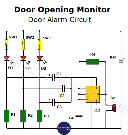
When a reed switch closes, it momentarily feeds the 555 timer through a resistor capacitor network. The 555 timer makes a buzzer sound for a very short time, warning audibly that a door is opened.
In other words, the buzzer warns that a door is open and the LED tells us which one was opened.
Different colors can be chosen for the LEDs and thus be able to differentiate the door that opens by means of its color. The circuit draws very little current and can be powered by a 9 V battery. It can also be powered by a power supply of the same voltage.

Real appearance and internal configuration of a “reed switch”. See that the switch closes only when the magnet is near.
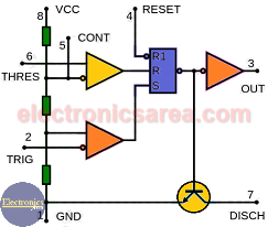
Internal 555 Timer Configuration
Circuit part list
- 1 x 555 IC (IC1)
- 3 “Reed switch” type switches, or another switch that performs the same function (SW1, SW2, SW3)
- 3 red LEDs (D1, D2, D3)
- 3 x 330 ohms resistors, 1/4 watt (R1, R2, R3)
- 1 x 1M resistor, 1/4 watt (R4)
- 3 x 470 uF (microfarad) electrolytic capacitors (C1, C2, C3)
- 1 x 0.1 uF (microfarad) capacitor (C4)
- 1 Buzzer (Bz)
- 1 9 V battery (Bat)
You may also like the Fridge Door Alarm Circuit.


