Logic circuits
A Logic circuit uses two logic levels to transfer the information. A high logic level or “1” and a low logic level or “0”. The Logic circuits are made of digital components such as the AND gate, the OR gate, the NOT gate and combinations of them.
These combinations of gates give way to other types of digital components, such as different logic gates, among others.
- NAND gate
- NOR gate
- Exclusive OR gate
- Mutiplexors
- Demultiplexors
- Decoders
- Encoders
- Memories
- Flip-flops
- Microprocessors
- Microcontrollers
- Etc.
Modern digital electronics is used to perform many functions. While digital electronic circuits might seem very complex, actually they are built with a very large number of very simple circuits.
In Digital electronics, the information is transmitted between circuits in a binary form (zeros and ones). The binary information is represented in the form of:
- “0” and “1”,
- “Open” or “Closed” (switch)
- “On” and “Off”
- “False” or “True”, etc.
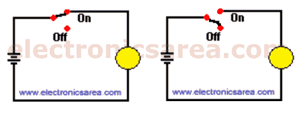
A logic circuit can be represented in many ways. In the following circuits, the lamp can be turned on or off, depending on the switch position.
A truth table is a tabular listing of all possible states of the switches (inputs) that affect the circuit and their corresponding output values.
More Digital Tutorials
- What is the difference between Analog & Digital?
- What is a logic circuit?
- Digital logic levels (high, low, 1, 0)
- The truth table
- Boolean algebra
- Karnaugh Map (K-map)
- Binary number system
- Hexadecimal numbering system
- BCD code – binary coded decimal
- Gray code – Gray code table
- Aiken code – Excess 3 code
- AND gate
- NAND gate
- OR gate
- NOR gate
- NOT gate
- XOR gate
- How to build a NAND gate with transistors & diodes?
- OR & AND logic gates made with diodes
- The combinational circuit
- The sequential circuit
- JK Flip-Flop
- What is a binary decoder?


