Light sensitive sound generator
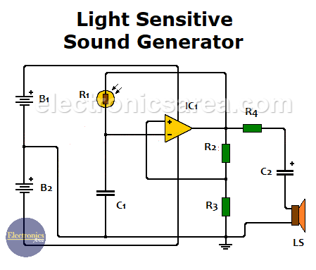
An oscillator circuit may have many applications. The diagram below shows how to make it work as a light sensitive sound generator using a LDR and a 741 operational amplifier.
How the Light sensitive sound generator circuit works?
To achieve our goal, we place a cadmium sulfide LDR between the pin 2 and the pin 6 of the 741 operational amplifier.
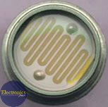
The LDR (Light dependent resistor) can be of any type, but it must have a resistance that is between 500 ohms and 5 megohms in normal working conditions. This will allow us to change the work frequency in a ratio of 10,000 to 1.
The variation of the LDR resistance, due to the change in light intensity, causes the frequency of the relaxation oscillator to change. This cause the sound of the speaker to change in the same way.
This circuit gives us a sound with a frequency that depends on the level of illumination that the LDR has. The greater the illumination on the LDR, the higher the frequency of the sound in the speaker will be.
LDR (Light dependent resistor)
The circuit is powered by two 9V batteries or a dual polarity voltage source (+ 9V/-9V).
741 Operational Amplifier
List of components for the light-sensitive sound generator circuit
- 1 741 operational amplifier (IC1)
- 1 cadmium sulfide LDR, (resistance between 500 ohms and 5 mega ohms). (R1)
- 2 100K resistors (R2, R3)
- 1 100 ohm resistor (R4)
- 1 0.01 uF (microfarads) capacitor (C1)
- 1 100 uF (microfarads) 18 V or more, electrolytic capacitor (C2)
- 1 8 to 25 ohms speaker
- 2 9V batteries
More Detector Circuits
- Light detector circuit using LDR (automatic night light)
- How to make a Light Sensitive Sound Generator Circuit?
- Light activated switch circuit with LDR and Op Amp
- Light Operated Relay Circuit using LDR / Photoresistor
- Twilight Switch Circuit
- Dark detector circuit using LDR and relay
- Darkness detector circuit with audio output using 555
- Temperature Gauge Circuit Using LM324 (PCB)
- Temperature to Voltage Converter using Thermistor (PCB)
- Rain Detector using two Transistors
- 2 LED Temperature Change Indicator with LM35 & 741
- Lie Detector Circuit Using Two Transistors
- Humidity sensor circuit using the 555 timer
- Blown Fuse Indicator Circuit using one transistor
- Electronic sound control Circuit (applause)
- Photodiode Amplifier Circuit – Current-to-Voltage Converter


