Tone generator using two 555 timers
This tone generator circuit uses the well-known 555 IC to generate a range of sounds that are heard through a small loudspeaker.
By handling the two potentiometers of the tone generator, you can change the oscillation frequencies of the two 555 timers that work as astable multivibrators, thus generating different sounds.
Operation of the tone generator with two 555 timers
The two 555 timers work as astable multivibrators. These multivibrators operate at different frequencies, having, the first multivibrator, a frequency much smaller than the second one.
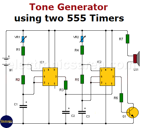
- The frequency of the first multivibrator depends on the potentiometer values VR1, resistor R2 and capacitor C1.
- The frequency of the second multivibrator depends on the potentiometer values VR2, resistor R5 and capacitor C2.
Resistors R1 and R4 are of low value and have almost no effect on the frequency.
The output of the first 555 (pin 3) is connected to the control input of the second 555 (pin 5) through the resistor R3. The square wave voltage of the output of the first 555 is applied to the pin 5 of the second 555 and allows varying the output frequency of the second timer, up and down the operating frequency set by the values of C2 and VR2.
In order to connect a speaker to the 555’s output, an NPN transistor (Q1) is used as a current amplifier. The connection is made by attaching pin 3 of the second 555 to the base of the transistor through the resistor R6.
The circuit uses a 9V battery or a power source with the same voltage.
Many modifications can be made to this circuit, and you should always bear in mind that for each timer:
- Increasing C will increase the cycle time (and hence, reduce the frequency).
- Increasing R1 will increase Time High, but will leave Time Low unaffected.
- Increasing R2 will increase Time High, increase Time Low and decrease the duty cycle (down to a minimum of 50%)
The oscillation frequency of the first timer is: F = 1 / [0.693 x C1 x (VR1 + 2 x R2)]
The oscillation frequency of the first timer is: F = 1 / [0.693 x C3 x (VR1 + 2 x R5)]
List of the tone generator circuit components
- 2 555 integrated circuits
- 4 1k resistor (R1, R2, R4, R5)
- 1 22k resistor (R3)
- 1 220 ohm resistor (R6)
- 1 22 ohms, 2 watts resistor (R7)
- 2 100k potentiometers (VR1, VR2)
- 1 4.7 uF (microfarads) electrolytic capacitor (C1)
- 1 1 uF (microfarads) electrolytic capacitor (C2)
- 1 0.047 uF (microfarads) electrolytic capacitor (C3)
- 1 2N3904 NPN transistor (Q1)
- 1 8 ohms or more, mini-speaker (LS1)
More Audio Circuits
- 2 watt audio amplifier with the TDA2822M IC
- 6 watt audio amplifier with TDA2613 (Hi-Fi)
- 400 watt stereo amplifier with STK4050
- 4-channel audio mixer using LM3900 IC
- Microphone mixer using operational amplifiers
- 6 LED VU meter using a single transistor
- Audio splitter – 1 Input – 4 Outputs
- Audio level indicator using LM339
- 8 LED VU meter using LM324 IC
- Music box using a CD4017 and Two 555
- Metronome with adjustable BPM
- Tone generator using two 555 timers
- How to add a tweeter to a baffle or speaker
- Guitar Synthesizer using CD4046
R7 at 22 Ohms is going to be dropping about five volts. Per Ohms Law, this means the resistor will be dissipating about 1.1 WATTS of power.
If you build this circuit with a typical hobbyist 1/4 watt resistor, it will burn out, as will Q1. Use at least a 2 watt resistor, higher if you have it.
Hi Eric
Thanks for notifying me of the error. I have already done the correction to the tutorial.
Thank you
regards