Light detector circuit using LDR
This light detector circuit activates a lighting device through a relay when the intensity of daylight is no longer sufficient. It can be used to illuminate the main entrance of the house, a display case that needs to be kept lit at night, an unsafe area at night, etc.
How does the light detector circuit work?
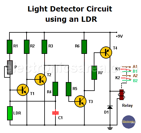
The light sensor element is a LDR (Light Dependent Resistor) whose resistance depends on the intensity of the incident light. The more light intensity, the less resistance in the LDR and vice versa. The potentiometer P is used to adjust the light level at which the relay connects to the lighting device.
Light detector circuit using LDR, transistors and a relay
- When the LDR is illuminated, its resistance decreases, transistor T1 enters the cut-off region, T2 enters the saturation region, and the base current of transistor T3 decreases. T3 and T4 enter the cut-off region. This has the effect that the relay will not be activated, and the lighting device will be turned off. Note that T4 is a PNP transistor.
- When the LDR is in the dark, its resistance is high, transistor T1 enters the saturation region, T2 enters the cu-toff region, allowing transistor T3 to be in the saturation region. T4 enters the saturation region and the relay is activated, and the light is turned on.
The relay uses a diode in parallel to prevent transistor T4 from being burned when the relay is turned off.
The circuit uses a 9 VDC power supply or a 9 V battery, but can be powered with 12 VDC (you must replace the relay with a 12 VDC one).
You may be interested in: Light Operated Relay Circuit using LDR
List of Components for the Light Detector Circuit
- 3 10K resistors (R1, R3, R6)
- 1 33K resistor (R2)
- 1 470 ohms resistor (R4)
- 1 100K resistor (R5)
- 1 2.2K resistor (R7)
- 1 470K potentiometer (P)
- 1 100nF capacitor (C1)
- 1 1N4004 diode (D1)
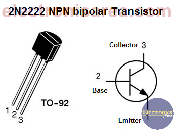
- 3 2N2222 NPN transistors (T1, T2, T3)
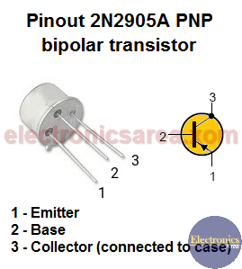
- 1 2N2905 PNP transistor (T4)
- 1 LDR (Light Dependent Resistor)
- 9 or 12 volt relay (depending on source voltage)
More Detector Circuits
- Light detector circuit using LDR (automatic night light)
- How to make a Light Sensitive Sound Generator Circuit?
- Light activated switch circuit with LDR and Op Amp
- Light Operated Relay Circuit using LDR / Photoresistor
- Twilight Switch Circuit
- Dark detector circuit using LDR and relay
- Darkness detector circuit with audio output using 555
- Temperature Gauge Circuit Using LM324 (PCB)
- Temperature to Voltage Converter using Thermistor (PCB)
- Rain Detector using two Transistors
- 2 LED Temperature Change Indicator with LM35 & 741
- Lie Detector Circuit Using Two Transistors
- Humidity sensor circuit using the 555 timer
- Blown Fuse Indicator Circuit using one transistor
- Electronic sound control Circuit (applause)
- Photodiode Amplifier Circuit – Current-to-Voltage Converter


