Home / Circuits / DIY Test & measuring /
How to test a Zener diode
It is common to use the same method to test Zener diodes as is used to test common diodes. That is, to see that the Zener allows current to pass when it is forward biased and that it does not pass when it is reverse biased.
The following method shows a simple way to test a zener diode.
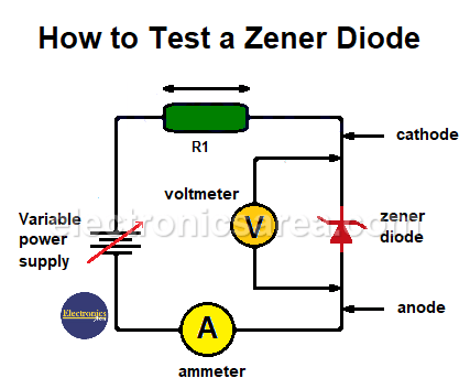
To test Zener diodes, a variable DC power supply is required. A simple circuit to perform this test is shown below:
How do I test a Zener diode – A simple method
The voltage source is used to adjust the input voltage to a suitable value for testing the Zener diode. Resistor R1 is used to limit the current through the diode.
Procedure to be followed when testing Zener diodes
1 – The Zener diode is in good condition when the following two points are met:
The Zener diode is connected as shown in the figure. The voltage is gradually increased from 0 volts, and current flows only until the voltage at the diode terminals equals the Zener voltage. In this case, the current flows from the cathode to the anode.
If the Zener diode is reverse-biased (connected in the direction of the diode arrow), current will flow easily through the diode and there will be a small voltage drop, usually less than 1 V. The current in this case flows from anode to cathode.
2 – The Zener diode is defective if the current flows easily in both directions and if there is a very small drop in the voltage.
Example of a method for testing Zener diodes
If we want to test a 12V zener diode, the output of the variable voltage source is regulated from minus to plus through 12V, 13V, and higher. If the diode is in good condition, the voltage at the diode terminals should be maintained at 12 V, regardless of whether the voltage at the power supply is higher.
If resistor R1 has a value of 100 ohms, the voltage drop across it will be 2 or 3 V (when the supply voltage is 14 or 15 V) and the current flowing will be 20 or 30 mA. If the position of the Zener diode is reversed, the voltage drop across it will be no more than 1 volt, causing the voltage across resistor R1 to be between 13 and 14 volts.
The current supplied by the source in this case will be a maximum of 140 mA. With these current values, a 100 ohm, 1/2 watt resistor can be easily placed.
How to find the voltage of an unknown zener diode?
You can also use this method to find the unknown characteristic voltage of the diode. In this case, the voltage at the diode terminals will stabilize at an approximately constant value as the variable voltage source is manipulated. The voltage at the diode terminals will be the zener voltage.
More DIY Test & Measurement Circuits
- How do I test a Zener diode? – A simple method
- Diode tester circuit with 741
- Audible continuity tester
- Continuity tester using 741 IC
- 555 Timer tester circuit
- Op Amp Tester circuit diagram
- How to protect the 500mA fuse of a multimeter?
- How to make a current flow indicator?
- How to measure Beta of a transistor?
- Logic Probe using NOT gates
- Acoustic Logic Probe using the 555 Timer
- Logic Probe with 7 segment display
- Logic Probe circuit using CD4001 IC
- Logic Probe using two transistors


