Home / Circuits / Controllers /
Thermistor Controlled Fan
This thermistor controlled fan circuit varies the speed of a fan connected to a 110 or 220 volts outlet, using just three transistors and a few additional components.
Caution: The circuit connects directly to 110/220 VAC, so there are parts that can be dangerous. Do the tests very carefully.
Thermistor controlled fan circuit operation
The sensor used for this circuit is a thermistor (R1), which is a resistor whose value depends on temperature.
The circuit consists of two voltage dividers, the first formed by the resistors R3 and R4 and the second formed by the thermistor R1 and the potentiometer.
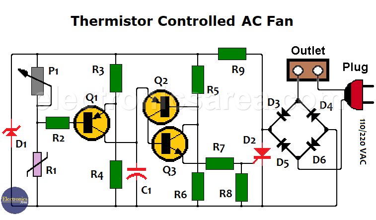
The first voltage divider creates a reference voltage of 2/3 of the supply voltage between the resistors and is connected to the emitter of transistor Q1.
The second voltage divider creates a variable voltage point due to the variation of the resistance of the thermistor R1. That point is connected to the base of transistor Q1.
The potentiometer is adjusted so that the reference voltage and the variable voltage are equal to a temperature just below that necessary to activate the transistor. In the above conditions, the base and emitter of transistor Q1 have equal voltages and the transistor does not conduct.
When the temperature across the thermistor rises, the value of the voltage across R1 drops below the reference value, causing transistor Q1 to conduct, send a voltage pulse, and charge capacitor C1.
The voltage with which the circuit is fed is 18 volts unregulated pulsating (there is no filter capacitor), and it is achieved with the resistor R9 and the Zener diode D1. Therefore, capacitor C1 delivers a phase-delayed pulse train that depends on temperature.
This pulse train is constant and has twice the frequency of the power distribution network (100 Hz / 120 Hz) and charges the capacitor continuously while transistor Q1 is activated due to the increase in temperature.
In this way, the voltage at the terminals of the capacitor activates the set of transistors Q2 and Q3 that form an activation device of the SCR D2 that now lasts longer.
You may also like:
Circuit component list
- 2 BC327 bipolar PNP transistors. (Q1, Q2)
- 1 BC337 bipolar NPN transistor. (Q3)
- 1 N.T.C. Negative temperature coefficient thermistor (R1)
- 1 linear potentiometer 22K (P1)
- 1 resistor 100K, 1/4 watt (R2)
- 2 10 K, 1/4 watt resistors (R3, R6)
- 2 resistors 22K, 1/4 watt (R4, R5)
- 1 resistor 100 ohms, 1/4 watt (R7)
- 1 resistor 480 ohms, 1/4 watt (R8)
- 1 33 K resistor, 5 watts for 220V AC or 15K, 2 watts for 110V AC (R9)
- 1 10 nF / 63 volt polyester capacitor (C1)
- 1 zener diode BZX79C18. 18V, 0.5 watts (D1)
- 1 SCR thyristor TIC106D 400V, 5 amps (D2)
- 4 rectifier diodes 1N4007 1000V, 1 Amp. (D3, D4, D5, D6)
More Controller circuits
- Water Level Controller using Transistor and Relay
- Automatic Water Level Controler
- Water level controller using NOR gates
- Differential Temperature Controller (PCB)
- Soldering Iron Temperature Controller
- Heat control using thermistor and TRIAC
- Thermistor Controlled AC Fan
- Electronic Thermostat using transistors
- H-Bridge DC Motor Control
- DC motor speed controller using 555
- DC Motor Speed Control with 4049
- Dimmer / AC Motor Speed Controller using TRIAC


