Home / Circuits / Controllers /
Electronic Thermostat Circuit using transistors
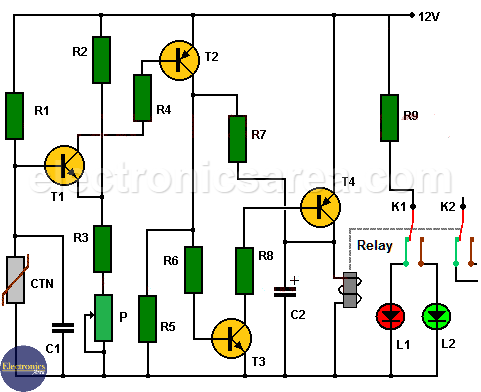
This electronic thermostat circuit allows us to control the temperature of a room, turning a heating device on and off. Very useful in winter and in very cold places.
The circuit uses a NTC thermistor (Negative Temperature Coefficient).
- If the ambient temperature is above the temperature set with the potentiometer, the relay does not activate and the green LED lights up.
- If the ambient temperature is below the temperature set with the potentiometer, the relay is activated and the red LED lights up.
Electronic thermostat setting
To properly set the temperature level at which the relay is activated, the potentiometer must be carefully adjusted. To adjust the electronic thermostat, the thermistor is inserted into a glass tube. The ends of the thermistor should be soldered to a pair of long wires.
Place the glass tube and a mercury thermometer in a container of water, which will be placed first in a refrigerator, then at room temperature, and finally on a gas burner or similar. The gas burner temperature must not be high. (see the temperature limits of the mercury thermometer).
In each case, locate the point where the red LED lights up, gently manipulating the potentiometer to maximum and marking on a screen (white card) behind the potentiometer, the temperatures read on the mercury thermometer.
How the Electronic Thermostat Circuit works?
The operation of the circuit is very simple and can be understood by analyzing the cutoff and saturation states of each transistor.
When the resistance of the thermistor is very high (the ambient temperature level is low), the transistor T1 goes into saturation, as long as the adjustment made in the potentiometer allows it.
If transistor T1 goes into saturation, transistors T2, T3 and T4 also saturate, activating the relay. This relay has double contact and each time it is activated it makes two connections, one to turn on the LED and the other to activate the heater.
Capacitor C1 is used to avoid sudden changes in thermistor value. Capacitor C2 is used to prevent sudden changes in voltage when the relay turns off, protecting the transistor.
You may also like: Over temperature alarm circuit using a Thermostat
List of circuit components
- 3 10K resistors (R1, R4, R6)
- 1 12K resistor (R2)
- 1 6.8K resistor (R3)
- 1 3.3K resistor (R5)
- 1 470K resistor (R7)
- 1 2.2K resistor (R8)
- 1 560 ohms resistor (R9)
- 1 10K linear Potentiometer (P)
- 1 10K NTC (Negative Temperature Coefficient) resistor
- 1 100nF capacitor (C1)
- 1 47uF, 16V, electrolytic capacitor (C2)
- 2 LEDs, 1 green, 1 red (L1, L2)
- 2 2N2222 NPN transistors (T1, T3)
- 1 2N2907 PNP transistors (T2)
- 1 2N2905 PNP transistors (T4)
- 1 12V relay with double contact output
More Controller circuits
- Water Level Controller using Transistor and Relay
- Automatic Water Level Controler
- Water level controller using NOR gates
- Differential Temperature Controller (PCB)
- Soldering Iron Temperature Controller
- Heat control using thermistor and TRIAC
- Thermistor Controlled AC Fan
- Electronic Thermostat using transistors
- H-Bridge DC Motor Control
- DC motor speed controller using 555
- DC Motor Speed Control with 4049
- Dimmer / AC Motor Speed Controller using TRIAC


