Home / Circuits / Controllers /
Water level controller circuit using CD4001 (NOR Gates)
This water level controller circuit controls the level of water in a tank. Unlike mechanical controls using a floating buoy, this circuit uses two sensors, an upper sensor and a lower sensor, as shown in the diagram.
The control circuit allows the entry of water to the tank, keeping the liquid level always below the upper sensor to prevent overflow.
This is necessary when you need to store water, which is then used in a system that uses gravity to distribute water. The circuit keeps the water tank, always full. This is the typical case of the Toilet Tank Water Level.
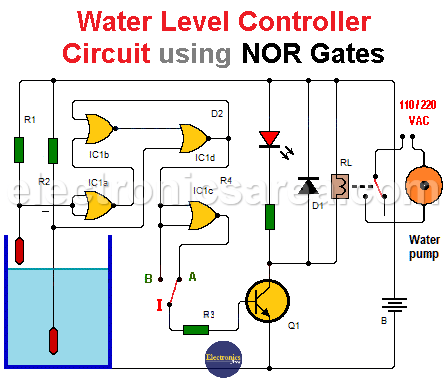
Water level controller circuit using NOR Gates
How the water level controller circuit works?
For the correct operation of the level control, the pump is activated when the lower level sensor no longer touches the water and is disabled when the upper level sensor touches the water.
This water level controller circuit also controls the flow of water from the tank, keeping the liquid level above the lower sensor and prevent the tank runs out of water. Water entering the tank may be due to rain, river, etc. This case becomes necessary when, for example, this tank serves to fill another tank.
It is also necessary to disconnect the pump, if the water level is low. A water pump that has no water can be damaged. To prevent this, the water pump is deactivated when the lower level sensor no longer touches the water and activated when the upper level sensor touches the water. The switch “I” connected to the base of Q1 through R3, to choose the desired option.
- On the “A” position, the system fills the tank with water.
- On the “B” position, the system drain water from the tank.
The relay must be able to directly activate an AC load (water pump) or alternatively activate a contactor which in turn activate the load.
List of components for the water level controller circuit
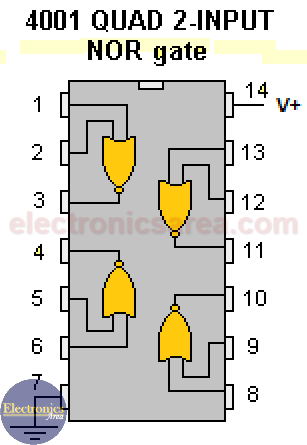
- 1 CD4001B two-input NOR gates (IC1)
- 1 BC338 NPN bipolar transistor (Q1)
- 1 1N4001 diode (D1)
- 1 red LED (D2)
- 2 47 K resistors (R1, R2)
- 2 1 K resistors (R3, R4)
- 1 12VDC relay with the adequate current capacity to control the contactor that turn on the pump. (RL1).
- 2 metal rods are used as sensors. Activation of the sensors is given when these are set to 0 volts through the water. We must remember that water is electrically conductive.
Notes:
- The tank or sensor in the tank wall (touching the water) must be grounded.
- The circuit is powered by a 12VDC voltage source.
More Controller circuits
- Water Level Controller using Transistor and Relay
- Automatic Water Level Controler
- Water level controller using NOR gates
- Differential Temperature Controller (PCB)
- Soldering Iron Temperature Controller
- Heat control using thermistor and TRIAC
- Thermistor Controlled AC Fan
- Electronic Thermostat using transistors
- H-Bridge DC Motor Control
- DC motor speed controller using 555
- DC Motor Speed Control with 4049
- Dimmer / AC Motor Speed Controller using TRIAC


")
