Home / Circuits / Controllers /
H-Bridge DC Motor Control Circuit
This H-bridge DC motor control circuit is used to control the direction of rotation of a direct current motor (DC motor) and is named after the letter “H” that forms the arrangement of transistors in the circuit.
The circuit is used to control medium-power motors due to the power limitation of the transistors.
H-Bridge DC Motor Controller Operation
The direction of rotation of the DC motor depends on the voltage levels that exist in the points of the circuit labeled as: “Forward” and “Reverse / Backward.” Only one of these two points can be high to activate the corresponding transistors.
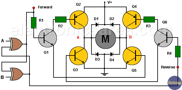
If the voltage level on the “Forward” label is high, transistor Q1 enters the saturation region, just like transistors Q2 and Q5. These two transistors allow current to flow through the DC motor in one direction.
If the voltage level on the “Reverse / Backward” label is high, transistor Q6 enters the saturation region, just like transistors Q3 and Q4. These two transistors allow current to flow through the DC motor in the opposite direction.
Diodes are placed to protect the transistors due to the polarity change in the DC motor windings.
Rotation control logic
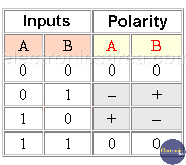
H-Bridge DC Motor Control System Truth Table
From the above discussion, it is understood that you should not have high voltage levels on both labels, so a small control circuit is used. This circuit is composed of two exclusive OR gates, and their operation (truth table) is shown in the previous image.
Pay attention to points A and B (in red), on the collectors of the transistors, to see the polarity of the voltage that is applied to the motor.
How do you control the H-bridge DC motor?
This circuit does not control the rotational speed of the motor. This could be controlled by varying the supply voltage of the circuit, or by using a Pulse Width Modulation (PWM) control.
Note: The supply voltage must be between 1.2 and 1.4 volts higher than the supply voltage of the DC motor due to the voltage drops in the base-emitter junctions of the conducting transistors.
Circuit component list
- 1 Exclusive OR Gate Integrated Circuit (74LS86)
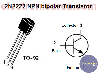
- 2 2N2222 or equivalent NPN transistors (Q1, Q6)
- 2 TIP32 or equivalent PNP transistors (Q2, Q4)
- 2 TIP31 or equivalent NPN transistors (Q3, Q5)
- 2 1K resistors (R1, R4)
- 2 27-ohm resistors (R2, R3)
- 4 1N4001 or equivalent diodes: (D1, D2, D3, D4)
More Controller circuits
- Water Level Controller using Transistor and Relay
- Automatic Water Level Controler
- Water level controller using NOR gates
- Differential Temperature Controller (PCB)
- Soldering Iron Temperature Controller
- Heat control using thermistor and TRIAC
- Thermistor Controlled AC Fan
- Electronic Thermostat using transistors
- H-Bridge DC Motor Control
- DC motor speed controller using 555
- DC Motor Speed Control with 4049
- Dimmer / AC Motor Speed Controller using TRIAC


