Home / Circuits / Controllers /
Automatic Water Level Controller Circuit
This automatic water level controller circuit ensures that there is always an adequate amount of water in the tank. There are many homes or buildings that do not have the necessary water pressure due to their geographical location.
In order to increase the pressure and to be able to reach everywhere, it is necessary to place an elevated tank, and thus the water is distributed by gravity.
A pump (motor) is used to move water from the ground to the tank. This pump is activated when the water level falls below a pre-set level and deactivated when it reaches a pre-set maximum level.
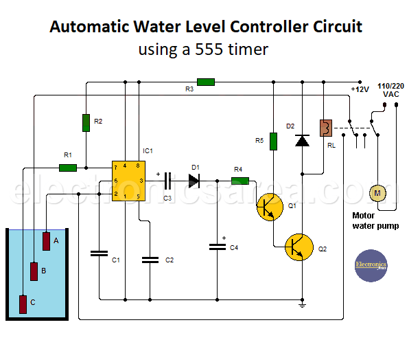
The tank has 3 sensors that indicate the amount of water in the tank to the controller circuit.
How does the automatic water level controller work?
When the water level rises:
1 – If the tank is low or has no water, neither sensor touches the liquid, or only the lower sensor touches the liquid. In this case, the pump is connected and pumping water to the high tank. Note that the pump is operating (its normal state) when the relay is not active.
In this case, the 555 outputs a high voltage level (approximately 10 to 11 volts) that does not saturate the transistors after passing through the network of capacitor, diode, and resistor.
Automatic Water Level Controller Circuit
2 – When the water reaches the level of the second sensor, there is no change, and the pump is still active, filling the tank.
3 – When the water reaches the level of the third sensor (the upper sensor), the 555 integrated circuit starts operating as an astable multivibrator. This multivibrator produces a continuous square wave at its output, which is rectified (half-wave rectification) and applied to the set of two cascaded transistors.
These transistors go into saturation and activate the relay, which in turn turns off the water pump and stops filling the tank.
When the water level drops:
The water level drops when water consumption starts.
1 – When the three sensors are still underwater (tank full), the relay is active and the pump is not connected (it does not pump water into the tank)
2 – When the top sensor is no longer underwater, the relay is still active and the pump is still not working (it is not pumping water into the tank).
3 – If the second sensor is no longer underwater, the relay is deactivated and the pump is turned on (water is pumped into the tank).
Thus, the process of filling and emptying the water is constantly repeated.
List of water tank level controller circuit components
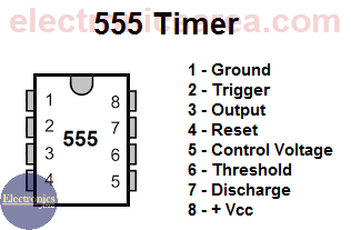
- 1 555 timer (IC1)
- 1 BC547 or similar NPN bipolar transistor (Q1)
- 1 2SD882, NTE184, or similar NPN bipolar transistor (Q2)
- 1 1N4148 or similar rectifier diode (D1)
- 1 1N4001 or similar rectifier diode (D2)
- 1 2-pole, double-contact, 12-volt relay (RL), capable of carrying water pump current
- A 56-ohm resistor (R1)
- 2 1K resistors (R2, R5)
- 1 100K resistor (R4)
- 1 10 Ohm resistor (R3)
- 1 0.1 μF (microfarads) capacitor (C1)
- 1 0.01 μF (microfarads) capacitor (C2)
- 2 4.7 μF (microfarads) electrolytic capacitors (C3, C4)
Notes:
- Water is used as a conductive path for electricity between the sensors, but since little voltage and current is used, it is not dangerous.
- The sensors can be small, well-polished metal rods connected to the circuit by thin wires.
- The circuit is connected to a 12 VDC source, but the voltage can easily be changed to 9 VDC. In this case, replace the relay with a 9V one.
More Controller circuits
- Water Level Controller using Transistor and Relay
- Automatic Water Level Controler
- Water level controller using NOR gates
- Differential Temperature Controller (PCB)
- Soldering Iron Temperature Controller
- Heat control using thermistor and TRIAC
- Thermistor Controlled AC Fan
- Electronic Thermostat using transistors
- H-Bridge DC Motor Control
- DC motor speed controller using 555
- DC Motor Speed Control with 4049
- Dimmer / AC Motor Speed Controller using TRIAC


