Home / Circuits / Controllers /
Water Level Controller Circuit
This simple Water level controller circuit is useful to control the water level in a tank. It does this by turning On and Off a water pump depending on the status of the sensors. With a NC (Normally Closed) or a NO (Normally Open) contacts of the relay RL, we can handle any type of starter.
How the water level controller circuit works?
The first time you power up the circuit, this immediately will activate the water pump. In the steady state.
- The NC relay contact keeps the starter on and thus the water pump On.
- The NO relay contact is open at the base of the transistor, then the transistor is in cut-off.
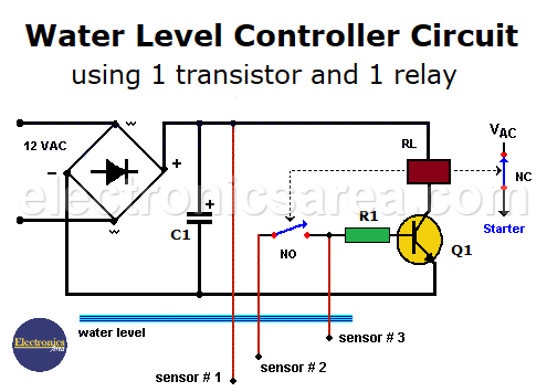
The first time you fill the tank, the water level will reach the first sensor. After that, it will always remain underwater. When the water level reaches the second sensor, nothing happens.
When the water level reaches the third sensor (the upper one), the transistor goes into saturation opening the NC relay contact, deactivating the starter and the water pump stops.
The NO relay contact closes, and locks the transistor in the saturation state.
When the water level drops and the top sensor is no longer in the water, the transistor remains in saturation because the NO relay contact remains closed, keeping the current flow on the base of the transistor. (The water pump is OFF)
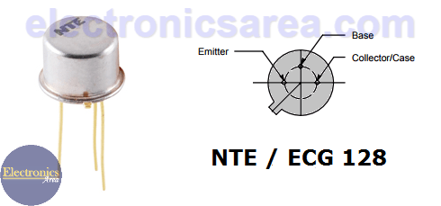
NTE128 NPN transistor pinout
When the water level is below the second sensor:
- The NO relay contact opens, and the transistor goes into cut-off.
- The NC relay contact closes, the starter turns ON and the water pump starts.
As you might guess, the top sensor “stops” the water pump, the second sensor “starts” the water pump.
The voltage in the water is between 12 and 15 VDC. This voltage is safe on outdoors water tanks. The distance between the circuit and the water tank can be up to 50 meters. (150 feet).
We use a 127VAC / 24VAC center tap transformer to get 12VAC, a 1 amp bridge rectifier and a 470 uF electrolytic capacitor. At the end, we get 16VDC volts to power the circuit.
Component List of the Water Level Controller Circuit
- 1 470 uF/40V electrolytic capacitor (C1)
- 1 ECG128 / NTE128 NPN transistor (Q1)
- 1 1 K resistor (R1)
- A 12VDC relay (you can use a NEMA size 0 Contactor to control the starter. The contactor can be up to 127 VAC, 220 VAC, 440VAC) (RL)
- Level sensors can be 5/16 or 1/4 inches stainless steel rods, with a nut for connection at one end and an isolated part from where you can grab it.
More Controller circuits
- Water Level Controller using Transistor and Relay
- Automatic Water Level Controler
- Water level controller using NOR gates
- Differential Temperature Controller (PCB)
- Soldering Iron Temperature Controller
- Heat control using thermistor and TRIAC
- Thermistor Controlled AC Fan
- Electronic Thermostat using transistors
- H-Bridge DC Motor Control
- DC motor speed controller using 555
- DC Motor Speed Control with 4049
- Dimmer / AC Motor Speed Controller using TRIAC


")
One of the simplest water level controller circuits I have ever come across! Great.
After seeing all the circuit I wondered simple circuit of all the function of ic circuit. Thanks for the brain. In this circuit no chattering or mal function of relay and operation is full proof.