Home / Circuits / Controllers /
DC motor speed controller circuit using a 555 timer.
This simple DC motor speed controller circuit works at 12 volts and controls a DC motor using a 555 integrated circuit. The timer 555 is used as a pulse width modulator (PWM) to vary the speed of the DC motor. Speed variation is achieved using the P potentiometer.
The 555 output controls the DC motor via transistors Q1 and Q2, which are connected in a Darlington configuration. The motor operates at 12 volts, with the current limited by the capacity of the output transistor.
How the DC motor speed controller circuit works:
The 555 operates in astable mode and has the additional feature of being able to modify the pulse width at pin 3 (the output).
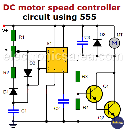
This is achieved using the D1 and D2 diodes, the R1 and R2 resistors, the potentiometer (P) and the capacitor (C1). These components regulate the charging and discharging times of capacitor C1, thereby determining the periods during which the 555 has a high or low output.
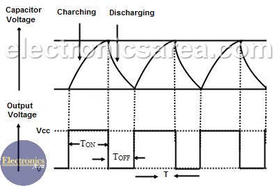
Since the output of the 555 IC is a square wave, the motor will have an output of:
- a period of time with 12 V or slightly less (Ton);
- a period of time with 0 V or a few millivolts (T_(off)).
The sum of Ton and Toff is equal to T, the period of the signal at the 555 output.
If the 555 has a longer high output (Ton), transistors Q1 and Q2 will remain in their saturation region for longer.
- Transistors Q1 and Q2 will remain in their saturation region for a longer time.
- The DC motor will have 12 volts between its terminals for a longer time.
- The DC motor will therefore spin faster.
If the 555 has a longer low output (Toff),
- The transistors Q1 and Q2 will be in their cutoff region for a longer time.
- The DC motor has 0 volts between its terminals for a longer period of time.
- The DC motor will spin more slowly.
Variation of the potentiometer from one end to the other will result in a transition from a stopped motor to a motor running at full speed.
List of components for the DC motor controller
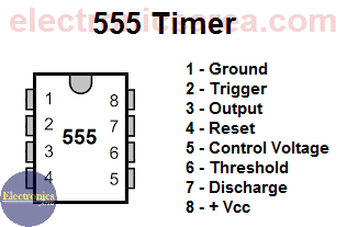
- 1 x 555 integrated circuit (IC).
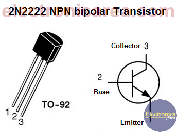
- x 2N2222 NPN transistor (Q1.
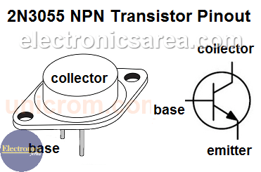
- 1 x 2N3055 NPN transistor (Q2).
- Two 1N914 diodes (D1 and D2).
- 1 x 1N4007 diode (D3).
- 2 x 2.2k, 1/4 watt resistors (R1 and R2).
- 1 x 1kΩ, 1/4W resistor (R3)
- 1 x 1.5 kΩ, 1/4 W resistor (R4)
- 1 x 1μF capacitor (C1)
- Two 0.1 µF capacitors (C2 and C3).
- 1 x 100 kΩ potentiometer (P1).
More Controller circuits
- Water Level Controller using Transistor and Relay
- Automatic Water Level Controler
- Water level controller using NOR gates
- Differential Temperature Controller (PCB)
- Soldering Iron Temperature Controller
- Heat control using thermistor and TRIAC
- Thermistor Controlled AC Fan
- Electronic Thermostat using transistors
- H-Bridge DC Motor Control
- DC motor speed controller using 555
- DC Motor Speed Control with 4049
- Dimmer / AC Motor Speed Controller using TRIAC


