Photodiode Amplifier Circuit – Current-to-Voltage Converter
A photodiode amplifier circuit, also known as a transimpedance amplifier, is indispensable in many applications and if the circuit is of high efficiency much better. If we take into account that the current generated by the photodiode is very small, being able to amplify the signal that it receives is very useful.
Although many op amps can be used to perform this amplification, the LM308 op amp is used because it has excellent gain, is more immune to noise than other op amps, and has better frequency response.
It must be taken into account that the voltage gain of an operational amplifier decreases with increasing frequency.
Photodiode Amplifier Circuit – Current-to-Voltage Converter
Photodiode Amplifier Circuit Operation
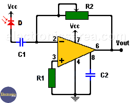
This very easy circuit is designed to receive pulses of light. If you want this amplifier to be used as a light detector, the capacitor C1 must be removed and the photodiode must be connected directly to the non-inverting input of the operational amplifier (pin 2).
This circuit is very sensitive and works very well as a receiver of light signals.
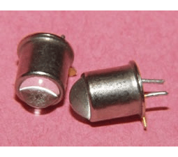
Photodiode – Light Detector Diode
The amplifier is configured as an inverting amplifier. This means that the waveform of the output is 180° out of phase with that of the input.
The gain of the amplifier can be controlled with potentiometer R2. Another way to look at this circuit is as a current-to-voltage converter (photodiode current to op-amp output voltage).
The output voltage of the op amp is the product of the photodiode current and the resistance R1. Capacitor C2 is used with the LM308 to improve its frequency response.
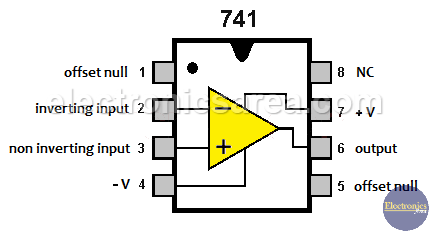
This circuit can work with the 741C op amp as well, but the gain and frequency response is lower. In this case the capacitor C2 is not necessary. The supply voltage can be between 6 and 15 volts.
Circuit component list
- 1 LM308T or 741C op amp
- 1 common photodiode (D)
- 1 1M (Mega ohm) resistor (R1)
- 1 1M (Mega ohm) potentiometer (R2)
- 1 0.01uF (microfarads) capacitor (C1)
- 1 100pF (picofarad) capacitor (C2)
More Detector Circuits
- Light detector circuit using LDR (automatic night light)
- How to make a Light Sensitive Sound Generator Circuit?
- Light activated switch circuit with LDR and Op Amp
- Light Operated Relay Circuit using LDR / Photoresistor
- Twilight Switch Circuit
- Dark detector circuit using LDR and relay
- Darkness detector circuit with audio output using 555
- Temperature Gauge Circuit Using LM324 (PCB)
- Temperature to Voltage Converter using Thermistor (PCB)
- Rain Detector using two Transistors
- 2 LED Temperature Change Indicator with LM35 & 741
- Lie Detector Circuit Using Two Transistors
- Humidity sensor circuit using the 555 timer
- Blown Fuse Indicator Circuit using one transistor
- Electronic sound control Circuit (applause)
- Photodiode Amplifier Circuit – Current-to-Voltage Converter


