Home / Circuits / DIY Test & measuring /
How to Make a Current Flow Indicator?
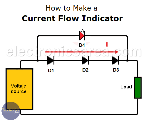
This Electric Current Flow Indicator gives a visual indication that there is a current flow. Possible applications for this small circuit may be: a battery charger, a voltage power source, etc. It works for DC current only.
In order to achieve our objective, we place 3 rectifier diodes in series, which in turn are in series with the load and battery.
How the current flow indicator works?
An “I” current flows through the rectifier diodes and there is an approximate voltage drop on them of 1.8 to 2.2 V. We have to remember that the voltage drop on a directly polarized diode can be between 0.6 to 0.7 volts. This range of voltage drops (1.8 to 2.2 volts on the 3 diodes) is sufficient for a LED to turn on.
The LED brightness remains constant throughout the range of currents “I” and reaches up to a maximum of 1 Ampere for the diodes that are used (1 ampere diodes).
As the voltage drop on the 3 diodes is between 1.8 and 2.2 volts, it is not necessary to use a current limiting resistor for the LED.
This Electric current flow indicator is inexpensive and reliable, however, approximately 2 volts are lost by the voltage drop across the 3 diodes. This voltage drop may not be important, but if it is, it may be taken into account in the design of the battery charger or voltage source, thus delivering 2 more volts.
Another way to test the flow of an electric current is to use a multimeter as an Ammeter testing DC current, but this method is more complicated, and the multimeter must be connected to the circuit all the time.
The circuit does not indicate the magnitude of the current being delivered. The idea is to indicate that there is current flow. If for some reason the demanded current is greater than 1 ampere, the rectifier diodes must be replaced by higher capacity ones. See the list of components below.
List of components for the current flow indicator
- 3 1N4001 or similar rectifier (1 ampere) (D1, D2, D3) or …
- 3 1N5808 or similar rectifier diodes (3 amps) (D1, D2, D3)
- 1 common red LED (D4)
More DIY Test & Measurement Circuits
- How do I test a Zener diode? – A simple method
- Diode tester circuit with 741
- Audible continuity tester
- Continuity tester using 741 IC
- 555 Timer tester circuit
- Op Amp Tester circuit diagram
- How to protect the 500mA fuse of a multimeter?
- How to make a current flow indicator?
- How to measure Beta of a transistor?
- Logic Probe using NOT gates
- Acoustic Logic Probe using the 555 Timer
- Logic Probe with 7 segment display
- Logic Probe circuit using CD4001 IC
- Logic Probe using two transistors


