Home / Power Supplies /
Current limiter circuit for Power Supply
When the amount of current required from a power supply exceeds its maximum capacity, we need a current limiter circuit. (Overcurrent protection)
The voltage regulator we use is made up of a zener diode and a pass-through transistor. If the current required in the load exceeds the maximum collector current of the transistor, the transistor can be damaged. To avoid this problem, it is necessary to have a circuit that protects against overcurrents.
How the Current Limiter (Overcurrent protection) work?
The circuit shown limits the current to a safe level. We have included a transistor and an additional resistor to the transistor-Zener voltage regulator (original circuit). When the voltage regulator is working, the current that passes through the load also passes through the resistor R.
The voltage across the resistor R is VR = I x R (Ohm’s law), and it is the same voltage of the base-emitter junction of transistor T2. The resistor R has a preset fixed value. The only situation that can make the VR voltage change is a change on the load current that passes through the resistor R.
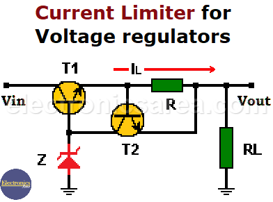
While the voltage across the resistor is below 0.7 volts, the transistor T2 is in its cut-off region, and the voltage source works normally. If there is an increase in the load current (IL), the voltage drop across resistor R increases as well. If the voltage across the resistor reaches 0.7 volts, the transistor T2 starts to conduct.
The collector of transistor T2 is connected to the base of transistor T1, which is the pass transistor of the regulator.
When the current in the load rises above a set maximum value, the transistor T2 begins to conduct and takes a bit of the transistor T1 base current, reducing the collector current IL (load current).
Note: Remember that Ic = β Ib. For a fixed β value, if we decrease the base current (Ib), the collector current (Ic) will also be decreased.
We can design a current limiter circuit like this for a predefined maximum current load.
For example:
1- We want to design a current limiter, and the maximum allowable current is 0.5 amps.
We know that the base-emitter voltage (Vbe) of transistor T2 is 0.7 volts and the allowed maximum current is 0.5 amps. The resistor to be used to achieve our goal is
R = Vbe / ILmax = 0.7 V / 0.5 Amps = 1.4 ohms. We can use a 1.5-ohm resistor.
The power of the resistor is (Joule’s Law):
P = I2 x R = 0.52 x 1.5 = 0.375 watts. We can use a 1.5 ohm, ½ watt resistor.
2- We want to design a current limiter and the maximum allowable current is 2 amps.
We know that the base-emitter voltage (Vbe) of transistor T2 is 0.7 volts and the allowed maximum current is 2 amps. The resistor to be used to achieve our goal is:
R = Vbe / ILmax = 0.7 V / 2 Amps. = 0. 35 ohms. We can use a 0.33-ohm resistor.
The power of the resistor is (Joule’s Law):
P = I2 x R = 22 x 0.33 = 1.32 watts. We can use a 0.33-ohm, 2-watt resistor.


