Metronome circuit using a 555 timer
This Metronome circuit, which uses a 555 timer and allows for adjustable BPM (beats per minute), enables musicians and students to maintain accurate timing for extended periods. It is crucial to maintain the rhythm of the music being played.
How does the Metronome circuit work?
The circuit could be a DIY audio project based on the well-known 555 IC, along with two transistors and some additional components.
In order to ensure consistent timing over an extended period, it is important to make appropriate adjustments. The circuit includes two trimmers (VR1, VR3), a potentiometer, and a transistor (Q1).
Transistor Q1 maintains the linearity of operation of the electronic metronome. The 555 timer operates in its astable configuration, and the output is handled through the PNP Q2 transistor and a typical 8-ohm impedance miniature speaker.
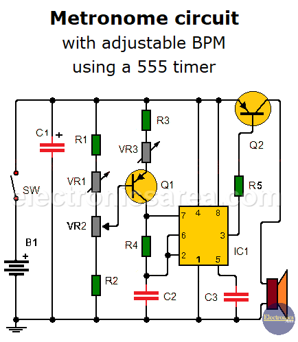
The frequency of pulses can be adjusted by varying potentiometer VR2 within the range of 20 to 208 pulses per second. Trimmer VR1 should be set to achieve a minimum of 40 pulses, while trimmer VR3 should be set to achieve a maximum of 288 pulses.
The Metronome circuit assembly is powered by a 12-volt battery or power supply with the same voltage. A portable metronome can be obtained by including the 12-volt power source in the same circuit.
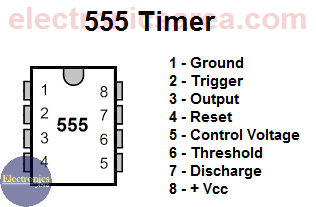
555 Timer Pinout
Metronome Circuit Components List
- 1 555 IC Timer (IC1)
- 1 PNP NTE 234 transistor (Q1)
- 1 PNP NTE 2658 transistor (Q2)
- 1 10 K resistor (R1)
- 1 330 K resistor (R2)
- 1 100 K resistor (R3)
- 2 1 K resistors (R4,R5)
- 1 10 K Trimmer (VR1)
- 1 50 K Trimmer (VR3)
- 1 10 K potentiometer (VR2)
- 1 100 uF electrolytic capacitor (C1)
- 1 1 uF capacitor (C2)
- 1 10 nF capacitor (C3)
- 1 Switch (SW1)
More Audio Circuits
- 2 watt audio amplifier with the TDA2822M IC
- 6 watt audio amplifier with TDA2613 (Hi-Fi)
- 400 watt stereo amplifier with STK4050
- 4-channel audio mixer using LM3900 IC
- Microphone mixer using operational amplifiers
- 6 LED VU meter using a single transistor
- Audio splitter – 1 Input – 4 Outputs
- Audio level indicator using LM339
- 8 LED VU meter using LM324 IC
- Music box using a CD4017 and Two 555
- Metronome with adjustable BPM
- Tone generator using two 555 timers
- How to add a tweeter to a baffle or speaker
- Guitar Synthesizer using CD4046


