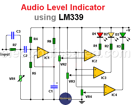
Audio level indicator using LM339
This audio level indicator using LM339 circuit is very interesting, since it allows us to visualize the intensity of the audio level by connecting this circuit to the input of a speaker.
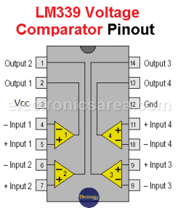
The LM339 integrated circuit has 4 comparators that operate completely independently, but share the same voltage source.
The voltage source may be in the range of 2 to 36 volts. This IC also works with two voltage sources +/- V (dual voltage source) as long as the sum of the two voltages is not greater than the maximum allowed.
How the audio level indicator works?
The circuit has three exits. Each of them is connected to an LED through a limiting resistor.
The green LED lights first when the signal voltage is low, then the yellow LED for medium signal levels, and when the signal level is higher, the red LED lights.
An LM339 integrated circuit is used to achieve our goal. This integrated circuit has 4 comparators that can be powered by a single polarity voltage source.
The input signal is applied to a resistor-potentiometer network which is used as a voltage divider, controlling the amplitude of the signal that is applied to the first comparator. C2 capacitor blocks any direct current voltage component.
The first comparator is used as a voltage follower. In this way, it is possible to have the same signal at the output as at the input.
The advantage of these voltage comparators is that they have a very high input impedance and do not load the output of the amplifier that sends the audio signal to the speaker.
The output of the first comparator is connected to the inverting input of the other three comparators.
The non-inverting inputs of the 3 comparators are connected to 3 potentiometers, which are used to set the voltage level that determines which LEDs will light.
Adjusting the four potentiometers in the circuit will achieve the desired effect.
You may be interested in the 8 LED VU meter circuit or the 6 LED VU meter using one transistor circuit
Circuit component list
- 1 LM339 IC, 4 comparators (IC1)
- 3 470 ohm resistors (R1, R2, R3)
- 1 330k resistor (R4)
- 1 1.2M resistor (R5)
- 1 470K resistor (R6)
- 1 100K potentiometer (VR1)
- 3 500K potentiometers (VR2, VR3, VR4)
- 1 1uF electrolytic capacitor (C1)
- 1 100nF (nanofarad) capacitor (C2)
- 3 LEDs, red, yellow, green (D1, D2, D3)
- 1 9 volts battery or a 9 volts voltage source
More Audio Circuits
- 2 watt audio amplifier with the TDA2822M IC
- 6 watt audio amplifier with TDA2613 (Hi-Fi)
- 400 watt stereo amplifier with STK4050
- 4-channel audio mixer using LM3900 IC
- Microphone mixer using operational amplifiers
- 6 LED VU meter using a single transistor
- Audio splitter – 1 Input – 4 Outputs
- Audio level indicator using LM339
- 8 LED VU meter using LM324 IC
- Music box using a CD4017 and Two 555
- Metronome with adjustable BPM
- Tone generator using two 555 timers
- How to add a tweeter to a baffle or speaker
- Guitar Synthesizer using CD4046


