Microphone Mixer using operational amplifiers
This Microphone Mixer using operational amplifiers combines signals from 3 different sources (3 microphones) easily and economically. This mixer can even work as an amplifier and portable mixer because of its few components.
How the microphone mixer work?
The circuit uses two operational amplifiers as main elements. The first operational amplifier works as a signal mixer and receives, at its inverting input, the three signals from the microphones.
We can adjust the amplitude (volume) of each of the input signals using the R4, R5, R6 potentiometers. This, prior to amplification of the combined signals, that makes the first operational amplifier (U1).
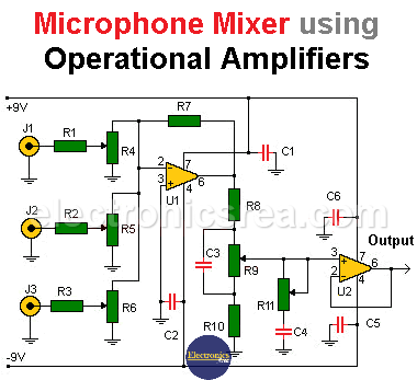
The output signal of the mixer is applied to a small network of resistors, potentiometers and capacitors in order to obtain the controls to adjust the sound.
The signal is subsequently applied to another operational amplifier, configured as a voltage follower. This allows the output impedance of the amplifier to be very low. To prevent external noise affecting the circuit, a capacitor is placed on each power input (-9 volts and + 9 volts). See diagram.
This simple circuit allows us to have a portable audio mixer that uses two 9-volt batteries
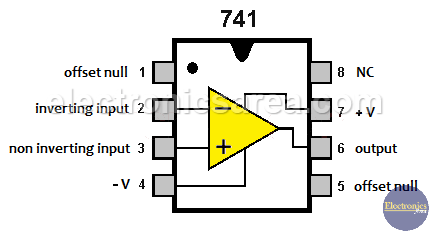
741 Operational Amplifier pinout
You may also like an 4-Channel Audio Mixer circuit
List of components for the microphone mixer circuit
- 2 741 operational amplifiers (U1, U2)
- 3 1K resistors, 1/4W (R1, R2, R3)
- 3 10K logarithmic potentiometers (R4, R5, R6)
- 1 1M resistor, 1/4W (R7)
- 2 10K resistors, 1/4W (R8, R10)
- 2 100K linear potentiometers (R9, R11)
- 4 0.1uF ceramic capacitors (C1, C2, C5, C6)
- 2 22nF ceramic capacitors (C3, C4)
More Audio Circuits
- 2 watt audio amplifier with the TDA2822M IC
- 6 watt audio amplifier with TDA2613 (Hi-Fi)
- 400 watt stereo amplifier with STK4050
- 4-channel audio mixer using LM3900 IC
- Microphone mixer using operational amplifiers
- 6 LED VU meter using a single transistor
- Audio splitter – 1 Input – 4 Outputs
- Audio level indicator using LM339
- 8 LED VU meter using LM324 IC
- Music box using a CD4017 and Two 555
- Metronome with adjustable BPM
- Tone generator using two 555 timers
- How to add a tweeter to a baffle or speaker
- Guitar Synthesizer using CD4046


