
4-channel audio mixer using LM3900
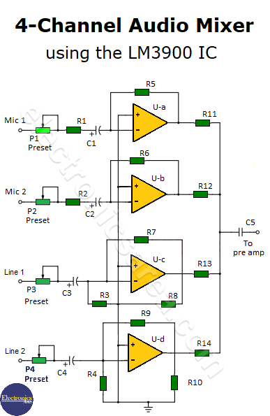
This 4-channel audio mixer uses the LM3900 integrated circuit, which has 4 operational amplifiers. This allows us to use a single integrated circuit and some resistors and capacitors to implement the audio mixer with a very simple design.
The circuit has two channels for microphone inputs and two channels for inputs of other devices. If you want a mixer with more input channels, you can duplicate this circuit and get a mixer with up to 8 channels.
You may also like to see this microphone mixer circuit.
The LM3900 operational amplifiers
The LM3900 operational amplifiers have the following characteristics:
- High amplitude output voltage.
- Low noise.
- Large bandwidth, which allows amplifying audio signals without problems.
- You can use voltage sources of +32 volts maximum or dual +/- 16 volts maximum.
- Short circuit protection.
- Etc.
How does the 4-channel audio mixer work?
The amplification of each channel
The amplification (gain) of each channel is controlled with 1 potentiometer. Four channels mean that we will use 4 potentiometers (P1, P2, P3, P4), placed at the inverting input of each amplifier. Each potentiometer controls the audio level of each channel before amplifying the signal and performing the audio mix.
The volume control
The potentiometers are used to control the volume of the input signals. The outputs of the 4 channels are mixed after passing through 4 resistors of the same value (R11, R12, R13, R14).
What are capacitors used for?
All operational amplifiers are configured as inverting amplifiers and have decoupling capacitors at their inputs and outputs. These capacitors filter (block) the direct current component of the signals at the input and output, amplifying only the alternating signal (the audio signal).
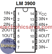
LM3900 Pinout (4 Operational Amplifiers)
List of components for the 4-channel audio mixer
- 1 LM3900 integrated circuit (4 operational amplifiers) (U1)
- 4 x 1k potentiometers (P1, P2, P3, P4)
- 2 x 0.1 uF (microfarad) electrolytic capacitors (C1, C2)
- 2 x 0.47 uF electrolytic capacitors (C3, C4)
- 1 x 0.1 uF capacitor (C5)
- 2 x 1 ohm, 1/4 watt resistors (R1, R2)
- 4 x 1 megohm, 1/4 watt resistors (R5, R6, R7, R9)
- 6 x 470 ohms, 1/4 watt resistors (R3, R4, R11, R12, R13, R14)
- 2 x 330 ohm, 1/4 watt resistors (R8, R10)
More Audio Circuits
- 2 watt audio amplifier with the TDA2822M IC
- 6 watt audio amplifier with TDA2613 (Hi-Fi)
- 400 watt stereo amplifier with STK4050
- 4-channel audio mixer using LM3900 IC
- Microphone mixer using operational amplifiers
- 6 LED VU meter using a single transistor
- Audio splitter – 1 Input – 4 Outputs
- Audio level indicator using LM339
- 8 LED VU meter using LM324 IC
- Music box using a CD4017 and Two 555
- Metronome with adjustable BPM
- Tone generator using two 555 timers
- How to add a tweeter to a baffle or speaker
- Guitar Synthesizer using CD4046


