The NOR Gate
The NOR gate is a logic gate that outputs a logic “0” in all combinations of its inputs except when they are all logic “0”, in this case the output is a logic “1”. See the truth tables in diagrams below.
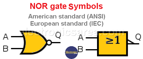
There are two accepted symbols for this gate. One of the American standard (ANSI) and another of the European standard (IEC).
A NOR gate can be implemented by concatenating an OR gate with a NOT gate, as shown in the following image.
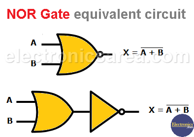
It can be seen that the output of the OR gate is: X = A + B. This output is passed through the inverter or NOT gate and is obtained: X = A + B.
NOR Gate Truth Table
As in the case of the OR gate, this gate can be found in versions with 2, 3 or more inputs.
- In TTL technology: 7402 (2 inputs), 7427 (3 inputs), etc.
- In CMOS technology: 4001 (2 inputs), 4025 (3 inputs), etc.
Truth tables for these two types of gates are as follows:
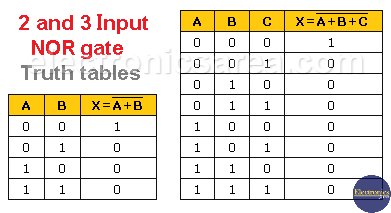
As you can see, the output X is only “1”, when all the inputs are “0”.
How to create a NOT gate with a NOR gate
Like the NAND logic gate, an interesting case of this gate is when inputs A and B or A, B and C (in the case of a 3-input NOR gate) are joined, to get a single input. In this case, the output (X) has exactly the opposite value of the input. View the first and last rows of the truth tables above.
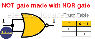
In other words: With a NOR gate, you can get the behavior of a NOT gate.
How to create a NOR gate with NAND gates
It is possible to create a NOR gate using NAND gates. Observing the following diagram it is seen that the inputs A and B are inverted after going through the first two NAND gates obtaining A’ and B’.
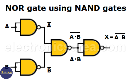
These two outputs serve as inputs for the third NAND gate, obtaining at its output (A’·B’)’. The output (A’·B’)’ is equivalent to A+B (De Morgan’s theorem). This last output is finally applied to the last NAND gate and to obtain the final output X = (A+B)’. The same output of a normal NOR gate.
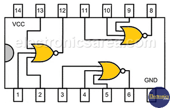
Below is the internal layout of the 7427 TTL IC, which has triple 3-input NOR gates. These gates have the 3-input truth table shown in a previous image.
More Digital Tutorials
- What is the difference between Analog & Digital?
- What is a logic circuit?
- Digital logic levels (high, low, 1, 0)
- The truth table
- Boolean algebra
- Karnaugh Map (K-map)
- Binary number system
- Hexadecimal numbering system
- BCD code – binary coded decimal
- Gray code – Gray code table
- Aiken code – Excess 3 code
- AND gate
- NAND gate
- OR gate
- NOR gate
- NOT gate
- XOR gate
- How to build a NAND gate with transistors & diodes?
- OR & AND logic gates made with diodes
- The combinational circuit
- The sequential circuit
- JK Flip-Flop
- What is a binary decoder?


