Home / Circuits / Timer circuits /
How do you get a perfect square wave with 555?
When a 555 timer operates as an astable multivibrator, it normally produces output pulses that are not in the form of a perfect square wave. A perfect square wave is defined as having the time at high voltage equal to the time at low voltage.
Circuits that produce a perfect square wave output can be somewhat complicated and unstable. However, a simple circuit like this one produces a stable perfect square wave.
At start-up, capacitor C1 is assumed to be discharged. Thus, a 0 V signal is applied to the internal comparator on the IC through pin 6 when power is applied to the circuit. Capacitor C1 is charged exponentially (by/through) resistor R1.
When the voltage on the capacitor (at pin 6) reaches 2/3 of the supply voltage, the timer’s internal comparator triggers the internal flip-flop, causing the output to go to 0 V or ground.
Now, capacitor C1 is discharged to 0V across resistor R1 until the voltage across the capacitor drops to 1/3 of the supply voltage, as seen on pin 2, the trigger input of the circuit. At this point, the IC’s internal flip-flop causes the output (pin 3) to return to the high voltage level (Vdc), restoring the circuit to its original state so that capacitor C1 is recharged.
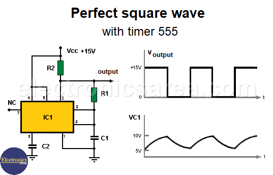
Joining the trigger pin (pin 2) and the threshold pin (pin 6) produces a continuous astable output, as these two pin levels alternately control the internal flip-flop and the integrated circuit output.
This also means that the charging cycle of the capacitor does not start at 0V as explained above, but can start at the negative slope of the voltage waveform across capacitor C1. (see figure)
This also means that the charging cycle of the capacitor does not start at 0 V as explained above, but can start at the negative slope of the voltage waveform on capacitor C1. (see figure)
Resistor R2 is a pull-up resistor that ensures that the voltage at pin 3 is approximately Vdc when the output is high.
Capacitor C2 is a bypass capacitor used when pin 5, the “voltage control”, is not used.
Yo may be interested on: Clock signal generator using the 7400 IC (PCB)
Formula for the Perfect Square Wave
The perfect square wave circuit with 555 works with the following formula:
t1 = t2 = 0.693 R1 x C1
T = t1+t2 = 1.386 R1 x C1
Thus, t1 and t2 have the same value and last for half the time of the period, which is T. Resistor R1 must have a value at least 10 times that of resistor R2.
Examples of how to use the formula to obtain a perfect square wave are as follows
For a frequency of 0.1 kHz.
C1 = 0.05 uF
R1 = 144.3 kΩ (calculated)
With R1 = 150 kΩ (actual), the frequency is: 0.0962 kHz.
For a frequency of 1 kHz.
C1 = 0.01 uF
R1 = 72.2 kΩ (calculated)
With R1 = 75 kΩ (actual), the frequency is: 0.962 kHz.
For a frequency of 5 kHz.
C1 = 0.01 uF
R1 = 14.4 kΩ (calculated)
With R1 = 15 kΩ (actual), the frequency is: 4.81 kHz.
For a frequency of 50 kHz.
C1 = 0.001 uF
R1 = 14.4 kΩ (calculated).
With R1 = 15 kΩ (actual), the frequency is: 45.3 kHz
List of components of the Perfect Square Wave circuit
- 1 555 timer integrated circuit (IC1)
- 1 kΩ resistor (R2).
- 1 0.01 uF capacitor (C2).
Based on the original article by Frank N. Cicchielo
More timer Circuits
- Perfect Square Wave – Formula – Examples
- High current pulse generator
- Electronic Doorbell Circuit (555 & CD4017)
- Automatic Night Light (555 & relay)
- Sound Activated Flash trigger (555 & LM386)
- Off-Delay Timer Circuit using 555 IC
- Time Delay circuit using (Triac & 555 IC)
- 5 to 30-Minute Timer Circuit (7555 IC)
- Long Duration Timer with NOR gates
- Missing pulse detector circuit (555 timer)
- ON-OFF Switch circuit using a 555 IC (PCB)
- Event Sequencer using the 555 timer


 - How to simplify Boolean functions")
