Home / Circuits / Timer circuits /
Sound Activated Flash trigger using 555 and LM386
With this sound activated flash trigger circuit, you can achieve incredible pictures of the most unexpected moments. Pictures like a water balloon that just burst and the water still floats in the air, or when an object of any type explodes.
In short, this circuit can capture moments that, because of its duration and the moment they occur, would be difficult to achieve otherwise.
The circuit shown below, performs this operation and can activate an electronic flash, for a period of time sufficient to take those amazing photos.
Sound activated flash trigger circuit operation
This circuit uses three main components
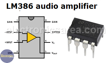
- A low power audio amplifier (LM386)
- A 555 Integrated circuit (555)
- A thyristor (SCR1)
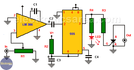
Note: capacitor C1 is connected between pins 1 and 8 of the lm386 amplifier.
A crystal microphone is ready to sense the sound that will activate the circuit (the microphone is connected to IN). When the event occurs, its sound is amplified by the LM386 audio amplifier, configured to have maximum gain.
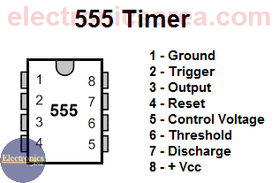
The amplifier output will then send a negative pulse to the input (#2 pin) of 555 IC. The 555 deliver, at its output (#3 pin), a voltage close to V+. The 555 IC, which is configured as a monostable multivibrator activates a thyristor (SCR) triggering the flash of the camera (OUT).
The 555 IC will have its output activated a time set by the 680K resistor (R2) and a 0.47uF capacitor (C3). 555 IC timer also prevents, repeated activations of the flash, during the output pulse of the integrated circuit. (The time when the output voltage 555 is at high level).
The LED gives a visual indication of flash activation. The circuit can be powered by a small battery of 9 volts. V+
List of circuit components
- 1 low power audio amplifier (LM386)
- 1 555 timer IC
- 1 SCR (200 Volts or more) (SCR1)
- 1 10 K potentiometer (10,000 ohms) (R1)
- 1 680 K resistor (R2)
- 2 1 K resistors (R3, R4).
- 1 10uF electrolytic capacitor (C1)
- 1 250uF electrolytic capacitor (C2)
- 1 0.47uF electrolytic capacitor (C3)
- 1 0.01uF ceramic capacitor (C4)
- 1 red LED
- 2 connectors (microphone and flash) (J1 and J2)
- 1 9 volt battery or same voltage source.
More timer Circuits
- Perfect Square Wave – Formula – Examples
- High current pulse generator
- Electronic Doorbell Circuit (555 & CD4017)
- Automatic Night Light (555 & relay)
- Sound Activated Flash trigger (555 & LM386)
- Off-Delay Timer Circuit using 555 IC
- Time Delay circuit using (Triac & 555 IC)
- 5 to 30-Minute Timer Circuit (7555 IC)
- Long Duration Timer with NOR gates
- Missing pulse detector circuit (555 timer)
- ON-OFF Switch circuit using a 555 IC (PCB)
- Event Sequencer using the 555 timer


