Home / Circuits / Timer circuits /
Long duration timer with NOR gates?
This long duration timer can be used to automatically turn off a television or radio or any other device after a period of time. For example, a good utility that can be given to this timer is the possibility of turning off the television for us in the event that we fall asleep.
The radio or TV automatically turns off after the programmed time, saving the cost of electricity consumption.
Long duration timer operation
With the values of resistor R3 and capacitor C1, we are able to achieve a delay of approximately 20 minutes. If the time obtained is not the desired one, or you want to set a different delay, you can vary the value of R3, C1 or both.
1. When push button B2 is pressed, electrolytic capacitor C1 discharges completely and the voltage between its terminals is zero. This voltage is applied to the inputs of the 4 NOR gates in parallel. These inputs have a very high input impedance, so they load the RC network.
With the gate inputs at zero volts (LOW), the gate outputs are at a high level (HIGH) making the transistor T conduct, activating the relay and turning on the LED.
2. When push button B2 is released, capacitor C1 starts charging across resistor R3, starting the delay time.
When the voltage across C1 reaches approximately half the power supply voltage, after the delay time has elapsed, the gate outputs, which were high (HI), go low (LOW).
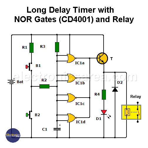
At this moment the transistor stops conducting, the Relay deactivates and the LED turns off, indicating that the programmed time has elapsed.
To start the long duration timer circuit it is best to press B2 for approximately 5 seconds before releasing it, to ensure that the capacitor is discharged.
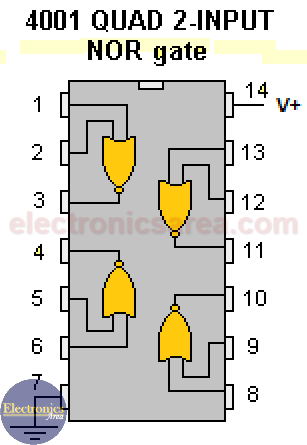
CMOS CD4001 Integrated Circuit – Internal Configuration and Pinout
Momentary push button B1 is used to reset the circuit and does so by fully charging the capacitor.
This causes the gate outputs to go LOW, putting the transistor in cut-off, disabling the relay and turning off the D1 LED, leaving the circuit ready to be used.
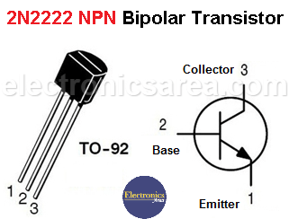
2N2222 NPN transistor pinout
Resistor R1 is included in the circuit to avoid a possible short circuit in the event that switch buttons B1 and B2 are pressed simultaneously.
Circuit component list
- 1 CMOS CD4001 integrated circuit, 4 2-input NOR gates. (IC1)
- 1 2N2222 NPN transistor or similar (T)
- 1 relay with voltage similar to that of the power supply with current capacity of 4 A or more.
- 1 100 ohm resistor (R1)
- 1 4.7K resistor (R2)
- 1 1M (mega) resistor (R3)
- 1 1K (kilohm) resistor (R4)
- 1 220uF (microfarads) electrolytic capacitor (C1)
- 1 red LED (D1)
- 1 1N4148 rectifier diode (D2)
- 2 momentary contact push buttons, normally open (NO) (B1, B2)
Note: This circuit can work with voltages between 6 and 12 volts, just use the same relay voltage as the power supply.
More timer Circuits
- Perfect Square Wave – Formula – Examples
- High current pulse generator
- Electronic Doorbell Circuit (555 & CD4017)
- Automatic Night Light (555 & relay)
- Sound Activated Flash trigger (555 & LM386)
- Off-Delay Timer Circuit using 555 IC
- Time Delay circuit using (Triac & 555 IC)
- 5 to 30-Minute Timer Circuit (7555 IC)
- Long Duration Timer with NOR gates
- Missing pulse detector circuit (555 timer)
- ON-OFF Switch circuit using a 555 IC (PCB)
- Event Sequencer using the 555 timer


