Clock signal generator using 7400 IC
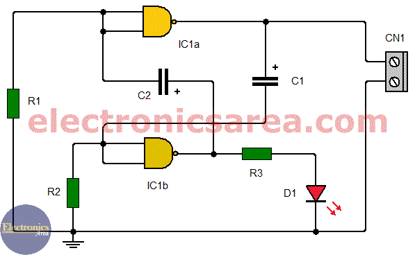
This clock signal generator using 7400 IC, is an astable circuit which uses the TTL 7400 integrated circuit. The 7400 IC has four 2 inputs NAND gates (NOT AND gate). We only use two gates of this integrated circuit.
This circuit is very useful. You can put all together and use it as part of a workshop or electronic laboratory. It can be used as a source of a clock signal. The signal generator circuit, as is implemented with TTL technology components, can only be connected to digital circuits of the same technology.
How the clock signal generator with 7400 works?
The two NAND gates, are connected as NOT gates, joining its two input terminals as shown in the circuit diagram.
Circuit operation sequence:
- With the capacitor C1 completely discharged, we have a logic “0” at the output of gate IC1a. This while the capacitor is charging through R2.
- This means that gate IC1b inputs are momentarily equal to logical “0”, and there is a logical “1” in the output.
- The pulse at the output of the gate IC1b is transmitted through the capacitor C2 to the input of the gate IC1a, and the output changes to logical “0”. This until the C2 capacitor is charging through R1.
- The capacitor C1, which was previously charged, is discharged and a logical “1” appears at the inputs of gate IC1b.
- With a logical “1” at inputs of gate IC1b, its output goes to logical “0”.
- And the cycle repeats …
LED lights intermittently, showing the correct operation of the circuit.
Clock signal generator printed circuit Board (PCB)
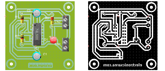
A suggested Printed Circuit Board (PCB) for the Clock signal generator using 7400 IC, is shown on the following diagram. The approximate result of the final circuit is also included.
List of components for the Clock signal generator
- 1 TTL 7400 / 74LS400 IC (IC1)
- 1 red LED (D1)
- 1 220 ohm resistor, 1/4 watt (R3)
- 2 1K resistors, 1/4 watt (R1, R2)
- 2 470uF / 16 V or more electrolytic capacitors (C1, C2)
- 2 connectors:
- 1 for the 5V power supply (CN2)
- 1 for the square wave output (CN1)


