Home / Circuits / Timer circuits /
Off-Delay Timer using a 555 IC
This off-delay timer is ideal when we want to schedule the automatic shutdown of a device after an established amount of time. For example, if we fall asleep while watching TV, there is no problem because this circuit turns off the TV.
This circuit can be implemented with the 555 timer. This integrated circuit is capable of producing delays from a few microseconds to several hours.
How does the off-delay timer work?
With this timer, the delays depend on an external resistor-capacitor (RC) arrangement. The 555 works in its monostable configuration and taking into account that internally the integrated circuit can function as a comparator.
One input of this comparator is connected to a voltage reference, which in this case is the output voltage of the power supply. (The positive terminal of capacitor C1). The other input of the comparator is connected to the external RC network. (R1, P and C2)
When the voltage across capacitor C2 equals the reference voltage, the comparator will toggle the 555 timer’s internal flip-flop (output pin 3). This output deactivates a relay, which in turn deactivates power at the outlet.
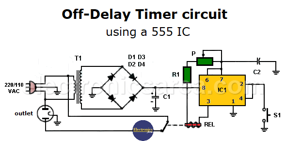
The relay must be 12 volts and have a very low current consumption. (less than 200mA).
The RC network is made up of the 100 microfarad capacitor C2 in series with a 5M potentiometer plus a 1M resistor. These values give a time delay ranging from three minutes when there is low resistance in the potentiometer to approximately 58 minutes when there is high resistance in the potentiometer. The manipulation of the potentiometer allows choosing the desired time.
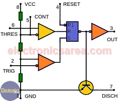
Pinout and Internal Structure of 555 Timer
S1 is a normally open (NO) momentary contact switch that is used to “reset” the timer so that time starts running again.
Off-delay Timer Component List
- 1 555 Timer (IC1)
- 1 transformer with secondary winding voltage of 6.3 Volts. (T)
- 1 1 Megohm resistor (R1)
- 1 5 Megohm potentiometer (P)
- 1 3000uF, 12V or more Electrolytic Capacitor.
- 1 100 microfarad capacitor, 15V or more.
- 1 12 V relay (REL)
- 4 1N4003 rectifier diodes (D1, D2, D3, D4)
- 1 normally open (NO) switch. (S1)
- 1 common use outlet.
Based on the article by: Pete Walton.
More timer Circuits
- Perfect Square Wave – Formula – Examples
- High current pulse generator
- Electronic Doorbell Circuit (555 & CD4017)
- Automatic Night Light (555 & relay)
- Sound Activated Flash trigger (555 & LM386)
- Off-Delay Timer Circuit using 555 IC
- Time Delay circuit using (Triac & 555 IC)
- 5 to 30-Minute Timer Circuit (7555 IC)
- Long Duration Timer with NOR gates
- Missing pulse detector circuit (555 timer)
- ON-OFF Switch circuit using a 555 IC (PCB)
- Event Sequencer using the 555 timer


