Electronics Area – Electrical and Electronics Tutorials and Circuits
Welcome to Electronics Area
Electrical and Electronics Tutorials and Circuits
Recent posts
Series and Parallel Inductors
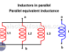
The equivalent value of a set of inductors connected in series or in parallel. These are the simplest methods for calculating the inductance of series and parallel inductors.
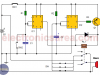
How to Make a Car Temperature Alarm using 741 and 555 ICs?
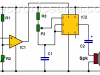
How to make a car temperature alarm?
This car temperature alarm check the car engine temperature and warns us, by means of a sound signal, when the temperature exceeds a seted value
What’s the Difference between Analog and Digital?

Difference between Analog and Digital. Digital refers to a discrete quantity. Analog refers to the quantities that vary with time on an ongoing basis.
Capacitor Discharging Process (RC circuit)
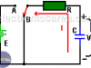
Capacitor discharge process. In a series RC circuit, a capacitor voltage Vc decreases from the initial voltage on the capacitor to 0 volts in some amount of time.
DC Motor Counter-electromotive force – Load Effect
Counter-electromotive force or Back-electromotive force
The voltage of a DC motor is divided into a voltage in the windings resistance and a voltage called Counter-electromotive force
DC Motor – Parts of a DC Motor. Basic Operation Principle.
DC Motor
A DC motor is composed of a stator and a rotor. In many small motors, the stator is composed of magnets. Larger motors have windings.
What’s Static Electricity? – Examples

Static electricity is static, since it is a current that is going nowhere. Both, DC and AC current flow in some direction, but static electricity does not.
Magnetic Field – Magnetic Field Lines
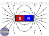
Magnets. Charges in motion (electric current) behave like magnets (produce magnetic fields)
AC motor (AC Electric Motor) – Poles – Windings Relationship
One of the characteristics of an AC motor is the number of rotor poles. This data will automatically give the number of windings that the motor has: # windings = # poles x 2.
Rain Alarm Circuit using 555 IC
Rain alarm circuit using 555
This Rain alarm circuit uses the water property to conduct electricity. To implement the water sensor we use two pieces of metal, which are placed close enough for a drop of water to let current flow between the metal plates
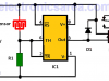
Car Burglar Alarm using two 555 timers
This is a simple Car Burglar Alarm circuit that uses a dual contact relay and two 555 timers, each of them working as a monostable multivibrator.
The alarm will activate the car horn, approximately 5 seconds after either door is opened and has not been properly closed.
Temperature effect on resistance

Temperature effects on resistance. The value of the resistance of a material varies with temperature change. For this reason, the circuit containing these elements should work in controlled environment