What are electronic filters?
Electronic filters are networks that allow or block the passage of a specific group of frequencies (frequency band).
Types of filters:
- Low pass filters
- High pass filters
- Band pass filters
- Band Notch filters
One of the main characteristics of both low-pass and high-pass filters is their cutoff frequency, which defines the group of frequencies that pass or do not pass through the filter.
- In a low-pass filter, frequencies below the cutoff frequency pass through the filter.
- In a high-pass filter, frequencies above the cutoff frequency pass through the filter.
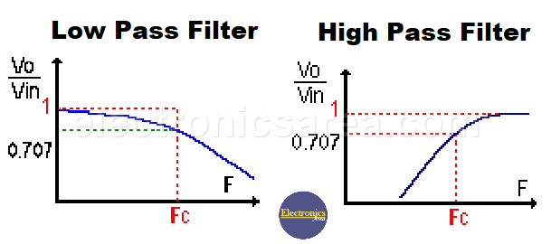
Low-Pass filter & High-Pass Filter – Transfer function vs. frequency
- In band pass filters, the main characteristics are: center frequency, bandwidth and quality factor.
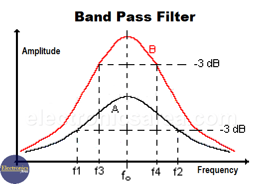
Band-Pass filter – Transfer function versus frequency
The curve A, in black, shows a center frequency fo (the resonance frequency). The bandwidth goes from f1 to f2. Curve B, in red, shows a center frequency fo (the resonance frequency). The bandwidth goes from f3 to f4.
The two curves are from two filters with the same center frequency. The frequencies used to determine the bandwidth (f1, f2, f3, f4) are called the cutoff or center frequencies and are obtained when the amplitude of the wave falls within 3 decibels (dB) of its maximum amplitude. See image.
Quality factor of a filter
Curve B shows a filter with higher selectivity because the cutoff frequencies are closer to the center frequency fo. In this case, the bandwidth of the filter is narrower.
Curve A shows a filter with lower selectivity because its cut-off frequencies are farther away from the center frequency fo. In this case, the bandwidth is wider.
(see the output amplitudes of the filters)
To find the quality factor of a filter, use the formula Q = fo /AB where
- fo = resonant frequency
- AB = bandwidth (f2 – f1) or (f4 – f3)
- In this case, filter B has a higher quality factor.
Filters – Order, Phase, Input/Output Ratio
A filter is a circuit with at least one reactive element (inductor or capacitor). A circuit with only one reactive element is a “first order filter”, if the circuit has two reactive elements it is a “second order filter”, and so on.
The difference between a first order filter and a higher order filter is the frequency response curve.
As you can see in the figure, the cutoff frequencies (f1 and f2 for the blue curve and f3 and f4 for the red curve) do not necessarily indicate that the frequencies to the left of f1 and f3 and to the right of f2 and f4 are completely eliminated.
In both cases, the curve slowly descends to its lowest level. Ideally, the filter should have a more square shape so that the unwanted frequencies are completely eliminated.
To achieve this, the order of the filters is increased (there are more reactive elements: coils and capacitors).
This type of filter is very useful in many cases, but there are others where the signal to be filtered is not very strong and loses energy as it passes through the different stages of the filter. In these cases, it is better to use “active filters”.
Phase and output voltage considerations
In an RC or RL filter, it is important to note that the phase difference between the voltage and the current (alternating) is between 0° and 90°.
This angle is precisely determined by the component values and the frequency in question. The formula is T = tan-1 (Xc /R) in the case of an RC filter.
- If Xc (capacitive reactance) were much larger than R (say about 100 times), then:
T = arctan (Xc /R) = tan-1 (100R/R) = tan-1 (100) = 89.5°. - If Xc (capacitive reactance) were much smaller than R (say about 100 times), then:
T = arctan (Xc /R) = tan-1 (Xc /100Xc) = tan-1 (1/100) = 0.5°. - If Xc and R have the same value, then T = tan-1 (Xc /R) = tan-1 (1) = 45°.
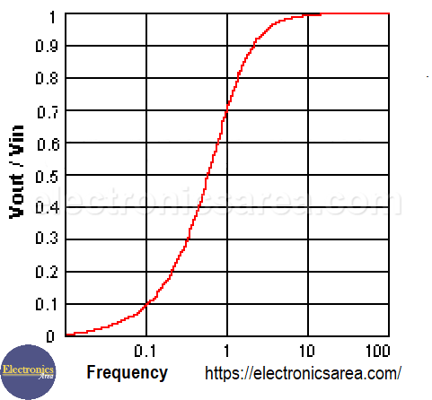
The output voltage of the filter depends on the frequency and amplitude of the input voltage.
A figure shows the ratio between the output voltage and the input voltage (Vout/Vin) for a frequency range (example for a high pass filter).
It can be seen that for low frequencies, the Vout/Vin ratio is practically “0”, indicating that the output voltage is very low.
On the other hand, for high frequencies, the Vout/Vin ratio is very close to “1”, indicating that the output voltage. Vout is practically equal to the voltage Vin.
This is the expected behavior of a high pass filter.
Note: arctan ( ) = tan-1( )
More Filters Tutorials
- Electronic filters – (low-pass, high pass, band pass
- RC Low Pass filter (passive low pass filter)
- RC High Pass filter (passive high pass filter)


