Home / Circuits / DIY Test & measuring /
How to protect the 500mA fuse of a multimeter?
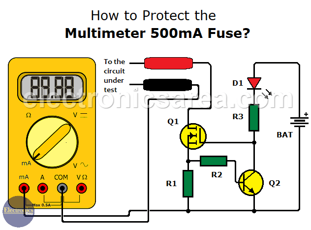
This is a very simple circuit to protect the 500mA fuse of a multimeter, due to the high frequency that these are burned.
In many cases, when measuring current, the 500mA limit is exceeded. This happens because we forget to change the red tip of the multimeter so that it can measure amps.
This circuit is very useful because it avoids having to open the multimeter to change the fuse, with all the loss of time that this entails, not to mention the fact that it is sometimes difficult to find a fuse with the same characteristics.
How does this circuit protect the 500mA fuse of a Multimeter?
This circuit acts as a current limiter of 500 mA (0.5 amperes).
When a current of 500mA flows through resistor R1, there is an approximate voltage drop of 0.75V across its terminals. This causes transistor Q2 to turn on and LED D1 to turn on, giving us a visual warning of the problem.
This LED and its associated limiting resistor can be replaced with a 9 V buzzer to change the visual warning to an audible warning. If you do not want any of the above warning options, you can replace the buzzer with a 10K resistor.
The gate voltage of the FET (VG) drops to a level where the source drain current (IDS) is limited to a safe value of 500 mA.
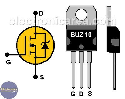
BUZ10 Power FET pinout
It is recommended to do some tests first to determine the final value of the R2 resistor and to obtain a maximum current lower than 500mA (e.g. 490 mA) to make sure that the fuse does not blow accidentally. It is also recommended to use a heat sink for the FET.
List of circuit components
- 1 BUZ10 power FET or similar (Q1)
- 1 BC547 NPN transistor or similar (Q2)
- 1 1.5 ohms resistor (R1)
- 1 1K resistor (R2)
- 1 330 ohms resistor (R3)
- 1 red LED (D1)
- 1 heatsink (FET)
- 1 9V battery (BAT)
More DIY Test & Measurement Circuits
- How do I test a Zener diode? – A simple method
- Diode tester circuit with 741
- Audible continuity tester
- Continuity tester using 741 IC
- 555 Timer tester circuit
- Op Amp Tester circuit diagram
- How to protect the 500mA fuse of a multimeter?
- How to make a current flow indicator?
- How to measure Beta of a transistor?
- Logic Probe using NOT gates
- Acoustic Logic Probe using the 555 Timer
- Logic Probe with 7 segment display
- Logic Probe circuit using CD4001 IC
- Logic Probe using two transistors


