Temperature alarm circuit with operational amplifier
This Temperature alarm circuit with operational amplifier activates a relay when the temperature of the place to be controlled exceeds a set level.
Possible applications for a temperature alarm circuit:
– An oven. It is desired that does not exceed a maximum temperature and prevent anything from burning.
– A cooling system for perishable foods. It is desired that the temperature does not exceed a maximum.
The temperature alarm circuit has an output relay. This relay can connect almost anything that will serve to warn of an emergency. This could be a sound device, a light (LED or bulb) etc. The relay can also trigger a system to disconnect for a while the heat source. See the following circuit.
Temperature sensors we can use are semiconductor diodes and thermistors. Thermistors are elements that change their resistance value depending on the surrounding temperature. Most thermistors are negative temperature coefficient (NTC) and have low resistance when the temperature is high and high resistance when temperature is low.
How the temperature alarm circuit works?
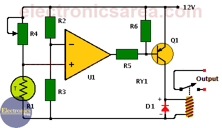
The circuit has two voltage dividers. The first consists of the thermistor R4 and potentiometer R1. The second consists of the resistors R2 and R3.
At the junction of resistors R2 and R3 (which have the same value) there is a voltage + V/2. As V + = 12 volts, this point has a voltage of 6 volts, and is connected to the inverting input of the 741 operational amplifier. The junction of thermistor R1 and R4 potentiometer is connected to the non inverting input of the 741 operational amplifier.
The operational amplifier acts as a comparator and “compare” the two voltage levels that are obtained from the voltage dividers. Under normal conditions, the output voltage of 741 is high (close to 12 volts). In this situation, the non-inverting input 741 has a higher voltage than the 6 volts of the inverting input.

741 Op-Amp Pin Configuration and Function
This is so because the sensed temperature is lower than the maximum limit and the resistance R1 has a value that makes the voltage at the non-inverting terminal is greater.
When the temperature rises, the thermistor value decreases, lowering the voltage at its terminals and causing the voltage at the non-inverting terminal to be less than 6 volts. This situation causes the comparator output to go low (near 0 volts), saturate the transistor Q1 and activate the relay, which, in turn, gives the alarm signal.
The R4 Potentiometer adjusts the temperature level at which the relay will be activated.
List of components for the Temperature alarm circuit
- 2 10K resistors (R2, R3)
- 1 10K potentiometer (R4)
- 2 1.2K resistors (R5, R6)
- 1 1K to 20K NTC thermistor (R1)
- 1 741 or similar operational amplifier (Op Amp) (U1)
- 1 2N3702 PNP transistor (Q1)
- 1 12V relay (RY1)
- 1 1N4007 semiconductor diode (D1)
Note: The temperature alarm circuit operates at 12 volts, but it can work with any other voltage without affecting its usefulness. We just have to respect the maximum supply voltage levels of the circuit components.
Other temperature alarms you may like:
- Over-temperature alarm using op amp
- Car Temperature Alarm using 741 & 555 ICs
- Over temperature alarm circuit using Thermostat
- Temperature Alarm u with thermostats