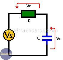
How a series RC circuit work?
In a series RC circuit connected to an AC voltage, the alternating current through the resistor and the capacitor are the same. The AC voltage VS is equal to the phasor addition of the voltage drop across the resistor (Vr) and the voltage drop across the capacitor (Vc). See the following formula: Vs = Vr + Vc.
This means that when the current is maximum (peak current), it is high in the resistor and the capacitor.
But something is different about voltages. In the resistor, voltage and current are in phase (maximum and minimum values coincide in time). But the voltage on the capacitor is not.
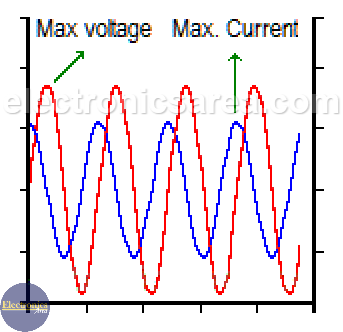
Capacitor lags current in series RC circuit
The capacitor opposes sudden voltage changes, so the voltage in the capacitor is delayed with respect to the current flowing through it. The maximum voltage in the capacitor occurs 90° after the maximum current value. These 90° are equal to ¼ wavelength, given by the frequency of the current passing through the circuit.
The total voltage of the series RC circuit is equal to the phasor addition of the resistor voltage and the capacitor voltage. This voltage has a phase angle (caused by a capacitor) and is obtained using the following formulas:
- Voltage value (magnitude): Vs = (VR2 + VC2)1/2.
- Phase angle: Φ = tan-1 (-VC / VR).
As stated before in a series RC circuit:
- The current leads voltage by 90 degrees in capacitor
- The current and voltage are in phase in a resistor.
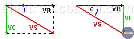
Using these data, we can construct the phasor diagram and the voltage’s triangle. With these diagrams we get the value and angle of the power supply (see above formulas).
The total resistance of the resistor-capacitor together, is called impedance (Z) and Z is the phasor addition (not an arithmetic addition) of the resistance values of the resistor and the reactance value of the capacitor. The unit of impedance is the “ohm”. The impedance (Z) is obtained using the following formula:
where:
- Vs: the magnitude of the voltage
- Φ1: the angle of the voltage
- I: is the magnitude of the current
- Φ2: the current angle.
How is the formula used?
The impedance value (Z), is obtained dividing the voltage Vs and current I. The angle (Φ) is obtained subtracting angle of “I” – angle “Vs”.
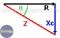
The same triangle voltages can be used if each value (voltage) of the triangle is divided by the current value, and thus the impedance triangle is obtained.
Note: parentheses raised to 1/2 = a square root.