Push – Pull Amplifier
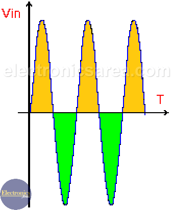
A Push – Pull amplifier is called that way, because it uses 2 groups of transistors and only one works at a time. One group pushes in one direction while the other pulls in another direction. Each group is responsible for amplifying a single phase of the input wave. See in the diagram.
One group is yellow and the other is green. (In this case there is only one transistor per group). When one transistor enters the saturation region the other enters the cutoff region and vice versa.
A common emitter amplifier configuration is used to amplify small signals. In this configuration the voltage of the output signal has practically the same amplitude as that of the input signal (unity gain) and they have the same phase.
When the input signal is large and you want to increase the current output capacity, a push-pull amplifier is used. (Power amplifier).
The push – pull amplifier shown in the following image is made up of two transistors. One NPN and another PNP with the same characteristics.
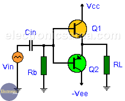
Push – Pull Amplifier Operation
The input signal is applied to the base of both transistors through the base pin of each transistor.
1 – Transistor Q1 has direct bias in the positive half-cycles (see yellow color) and the input signal goes through RL (load resistor). The output signal follows the input (this means that the input signal and output signal are in phase).
In positive cycles (yellow color) the Q2 transistor turns off and no signal goes to the output (it looks like the output of a half-wave rectifier).
2 – In negative cycles (green color) transistor Q1 turns off and no signal goes to the output (it resembles the output of a half-wave rectifier).
Transistor Q2 has direct bias in the negative half cycles (see green color) and the input signal goes through RL. The output signal follows the input (they are in phase).
From the third diagram, it is observed that the output wave is distorted (see near the horizontal axis). This distortion is due to the 0.6 volt voltage drop between the base and emitter of transistors Q1 and Q2. This is a very low distortion so many times it is neglected.
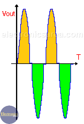
Note: The maximum value of the output signal will always be less than the maximum value of the input signal due to the base-emitter voltage drop in both transistors. (the gain is always slightly less than 1).
In other words there is a slight voltage attenuation, but a large current gain and consequently a power gain.

")
")
