Parallel RC circuit
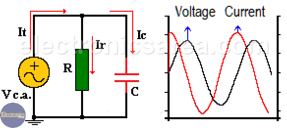
In a parallel RC circuit:
– The voltage is the same on the capacitor and resistor.
– The value of the current delivered by the voltage source, is divided between the resistor and capacitor. (It = Ir + Ic). See the first diagram below.
Current through the resistor and voltage on it, are in phase because the resistor does not cause any lag.
Current is ahead of the voltage in the capacitor, which is the same to say that voltage is delayed with respect to the current. As we already know: The capacitor is opposed to abrupt changes in voltage.
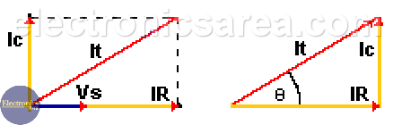
The magnitude of the total alternating current is equal to the addition of the current through the capacitor and the current through the resistor. This total current value and the phase angle are obtained using the following formulas:
- Magnitude of the total current: It = (Ir2 +Ic2)1/2
- Current phase angle: Θ = Arctan (-Ic/Ir)
See the following vector diagram of currents:
The impedance “Z” of the parallel RC circuit is obtained using the formula:
![]()
How the formula is applied?
- “Z” is obtained by dividing V by I.
- The angle (Θ) of “Z” is obtained by subtracting the angle of the current “I” from the angle of the voltage “V”. This angle is the same as shown in the diagram above and is given by the formula: Θ = Arctan (-Ic/Ir).
Notes:
- The square root is the same as a parenthesis, raised to the 1/2.
- Arctang() = tan-1()