Sep 182014
Wien-bridge Oscillator using Op-Amp
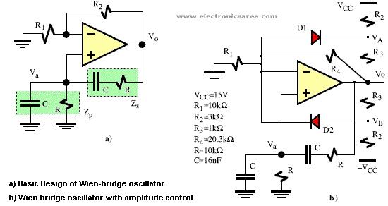
The Wien-bridge oscillator, as shown on the basic outline of the diagram below, consists of an Operational Amplifier (OA) in a non-inverting configuration with gain 1+R2/R1 and a RC feedback network with the following transfer function:
Where:
Combining the first and the second equation we get:
The loop gain (BA) is:
The Barkhausen criterion defines the conditions for oscillation at frequency ƒo:
To ensure the conditions of oscillation, R2/R1 must be chosen slightly higher than 2 to correct small variations in the circuit.
Furthermore, the amplitude of oscillation can be determined and stabilized using a nonlinear circuit as shown in picture above. The diodes D1 and D2 and resistors R2 and R3 act as limiting the output amplitude.


